Page 59 - Industrial Plants 2014
P. 59
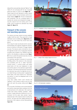
shipyard they were painted, renamed “Alpha A” and
“Alpha B” and connected with the two crosshead
beams by means of a 200 ton crane (figure 16).
Fagioli engineered and fabricated a wedge shaped
structure to better connect the beams with the two
barges offshore (figure 17). The set of strand jacks
were positioned onto the crosshead beams for
lowering the caissons and alongside the barges to
drag the caissons from the building yards to the
canals, once in position the catamaran was ready
(figure 18, figure 19).
Fig. 16 - Installation of the crosshead beams
Transport of the caissons
and launching operations
The caissons are huge cement structures weighing
roughly 12,000 ton each. They were built in a huge
dried basin used as building yards (figure 20) pretty
close to the canal where they should have been
placed.
Once ready, the basin was flooded and the caissons
started floating, two tugboats dragged the caissons
(once at a time) out of the basin in a bigger repaired
sea area. The caissons were connected not only to
the tugboats but also to four mooring lines resistant
propylene wires hooked to four SPMTs (6 axle lines
each) on the shoreline as safety procedure (figure
21). Once in position the tugboats were disconnected
and hooked to the catamaran. Fig. 17 - Detail of the wedge shaped structure
The launching operations consisted of connecting
the lifting points of the caissons to the catamaran
and proceeded with the so called “secondary
mooring system”, a mooring system with pulling
strand jacks L50 that was engineered to keep
secured the caisson to the catamaran against lateral
movement. Once the structure had been connected,
the catamaran was pushed by tugboats and joint to
a so called “primary mooring system” equipped with
strand jacks L300 which allowed the “catamaran
and caisson” to reach the designated area for the
sinking operations.
Long wires (called “trench axis”) showed the
“pathway” or line to follow in order to get out of the
basin and reach the precise sinking point (figure Fig. 18 - 3D Catamaran rendering
22).
Once in position, the floating caissons were ballasted
and sunk by using strand jacks positioned onto the Fig. 19 - Fagioli catamaran
crosshead beam on the catamaran. After reaching a
certain level during lowering operation, “water
cushions” (bags) previously positioned by the civil
contractor into the water were opened, “gently”
taking the load of the caissons before touching the
ground. The bags were then deflating allowing the
placement of the caissons at their final positioning
(figure 23).
IndustrIal Plants - May 2014
55