
Page 26 - Industrial Plants
P. 26
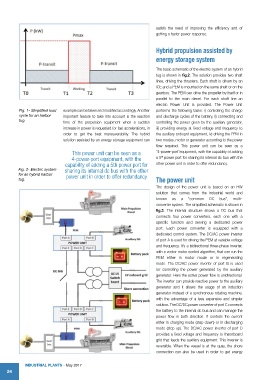
satisfy the need of improving the efficiency and of
                                                                      getting a faster power response.


                                                                      Hybrid propulsion assisted by
                                                                      energy storage system

                                                                      The basic schematic of the electric system of an hybrid
                                                                      tug is shown in fig.2. The solution provides two shaft
                                                                      lines, driving the thrusters. Each shaft is driven by an
                                                                      ICE and a PEM is mounted on the same shaft or on the
                                                                      gearbox. The PEM can drive the propeller by itself or in
                                                                      parallel to the main diesel.  For each  shaft line  an
                                                                      electric  Power Unit is provided. The Power Unit
          Fig. 1- Simplified load   example can be taken and modified accordingly. Another   performs the following tasks: i) controlling the charge
          cycle for an harbor   important feature to take into account is the reaction   and discharge cycles of the battery, ii) connecting and
          tug.               time of the propulsion equipment  when a sudden   controlling the power given by the auxiliary generator,
                             increase in power is requested for fast accelerations, in   iii) providing energy at fixed voltage and frequency to
                             order to get the best maneuverability.  The hybrid   the auxiliary onboard equipment, iv) driving the PEM in
                             solution assisted by an energy storage equipment can   two modes, motor or generator according to the power
                                                                      flow required.  This power unit  can be seen as a
                                 This power unit can be seen as a     “4-power-port”equipment, with the capability of adding
                                                                         th
                                 4-power-port equipment, with the     a 5  power port for sharing its internal dc bus with the
                              capability of adding a 5th power port for   other power unit in order to offer redundancy.
         Fig. 2- Electric system   sharing its internal dc bus with the other
         for an hybrid harbor   power unit in order to offer redundancy
         tug.                                                         The power unit
                                                                      The  design of the  power  unit is  based  on an HW
                                                                      solution that comes from the  industrial world and
                                                                      known  as  a   “common  DC  bus”,  multi-
                                                                      converter system. The simplified schematic is shown in
                                                                      fig.3.  The internal structure shows a DC bus that
                                                                      connects four power converters, each one with a
                                                                      specific function  and  serving  a  dedicated  power
                                                                      port.  Each power converter is  equipped with a
                                                                      dedicated control system. The DC/AC power inverter
                                                                      of port A is used for driving the PEM at variable voltage
                                                                      and frequency. It’s a bidirectional three-phase inverter,
                                                                      with a vector motor control algorithm, that can run the
                                                                      PEM either in motor  mode  or in regenerating
                                                                      mode.  The  DC/AC  power  inverter of  port  B  is used
                                                                      for  controlling the  power generated by  the auxiliary
                                                                      generator. Here the active power flow is unidirectional.
                                                                      The inverter can provide reactive power to the auxiliary
                                                                      generator and it  allows  the  usage  of  an  induction
                                                                      generator instead of a synchronous rotating machine,
                                                                      with the advantage of a less expensive and  simpler
                                                                      solution. The DC/DC power converter of port C connects
                                                                      the battery to the internal dc bus and can manage the
                                                                      power flow in both direction. It controls the current
                                                                      either in charging mode (step down) or in discharging
                                                                      mode (step up). The DC/AC power inverter of port D
                                                                      provides a fixed voltage and frequency to theonboard
                                                                      grid that feeds the auxiliary equipment. This inverter is
                                                                      reversible. When the vessel is at the quay, the shore
                                                                      connection  can  also  be  used  in  order  to  get  energy


            IndustrIal Plants - May 2017
    24