
Page 80 - 85
P. 80
Excellence
Focus Oil&Gas INFORMAZIONE PUBBLICITARIA in Performance & Reliability
www.indra.it indra@indra.it
Ball & DBB Split body Floating, Instrumentation Valves & Manifolds
Trunnion & Actuated Valves
indra
Progettazione e realizzazione
Monoflanges Valves
di valvole ‘tailor made’ Integral one piece Floating Slim line SB - SBB - DB - DBB
Ball & DBB Valves
Ball & DBB Valves
Fondata nel 1987, Indra è all’avanguardia nella Sampling & Injection DBB Valves Customized configuration
Customized configuration
progettazione e realizzazione di valvole a sfera e spillo
in varie configurazioni e diametri, da versioni double
block & bleed integrali e split body a manifold per stru-
mentazione, costruite secondo i più elevati standard
qualitativi di sicurezza ed efficienza.
L’esperienza nel comprendere i ‘tipici’ delle installa-
zioni, le scelte di innovazione e la massima versatilità,
consentono a Indra di elaborare delle soluzioni perso-
nalizzate, secondo le specifiche esigenze della cliente-
la, seguendo quindi un approccio “tailor made”.
Tutti i prodotti vengono realizzati nei materiali più ri- Application
correnti ed “esotici” per applicazioni critiche (Duplex, • riduzione dei costi;
A
T
B
6
I E
P
PA
A
8
1
9
0
3
4
E
4
I 5
.
1
D CONSTRU
1
/
9
ASME/ANSI B16.34
e
3
I
8
N
NS
.
Fire Safe CONSTRUCTION CONSTRUCTION STRUCTION I B16.34
SS 316/316L,
I 5
P
/
.
MA
6
B
1 PRODUCT
P
/
8
A
CONSTRUCTION
4
A
PRODUCT afe
e
3
9
2
P
5
UNI EN I
4
:
ER
2
I 5
MATERIALS
COMPANY
I 5
A
A
A
U
2
D
0
S
S
A
ME
I 5
E
6
P
T
NS
0
1
4
I
6
D
0
8
E
N
2
N I
COMPANY I EN ISO 9001:2015U-TR 010/2011
/
AL
CONSTRUCTION
I
ER
MA
/
N
1
U
6
B
P
1
9
A
0
Y
S
SS 316/316L, MATERIALS API 598 ASME/ANSI B16.34 CONSTRUCTION PED 2014/68/EU EAC-CU-TR 010/2011 Fire Safe PRODUCT UNI EN ISO 9001:2015 COMPANY COMPANY COMPA COM COMPANY N ISO 9001:2015 UNI EO 9 UNI EN ISO 9001:2015 PRODUC PRODUC T Fi r e S Fire Saf Fire U Fire Safe Safe EAC-C UNI EN ISO 9001:2015 PRODUCT EAC-CU-TR 010/2011EAC-CU-TR 010/2011EAC-CU-TR 010/2011PED 2014/68/EU PED 2 PRODUCT Safe /68/EUCTION CON ASME/ANS EAC-CU-TR 010/2011/
4
0
E
/
0
T
S
1
2
S
O 9
:
ER
Fi
P
P
Y
U
1
5
6
0
8
9
0
8
8
8
ME
T
/
N
A
0
4
1
I
/
S
T
r
6.34
1
NS
MA
1
E
PED 2014/68/EUTERIALS SS 316/316L,
ME
S
S &
C
I
TI
9
CERTIFICATIONS
A
N
0
N
A
ISO 104
S
M
CERTIFICATIONS
C
7
S
I
NORMS &
N
4
O
O 1
TI
CERTIFICATIONS
I
9
I 6
F
4
C
Duplex F51, SuperDuplex
S
P
A
N
7
0
F
–
F
P
A
For EAC Countries
S
I 6
–
9
7
O
A
TI
Duplex F51, SuperDuplex NORMS & Super Duplex, Monel...). ISO 10497–API 607–API 6FA CERTIFICATIONS • protezione della linea da sovrappressioni; CERTIFI CERTI CERTIFICATIONS CERTIFICATIONS CERTIFI CERTI CERTIFICATIONSAPI 607–API 6FA – ISO 10497–API 607–API 6FAtries For EAC C o FoC C i e A s o u C C n t o r i u e s n t r i e s CERTIFICATIONS–API 607–API 6FAMS & O R M N O S & M S & o r E A C C o For EAC Countries Duplex F51, SuperDuplex Duplex F51, SuperDup
4
R
I 6
NORMS & Duplex F51, SuperDuplex
7
–
P
A
TI
O
CERTIFICATIONS
7
O 1
0
N
For Eu
S
A
7
F
n
o
F
u
N
O
R
r
R
0
O
CERTIFICATIONS
n
ISO 10497–API 607–API 6FAuntries
r E
t
N
A
r E
I
o
C
9
–
A
O
C C
A
0
F
I 6
P
A
ISO 1A
/
.
6D
1
NS
20
A
A
PI
1
A
.
PI
ASME/ANSI B1.20.1
N ASME/ANSI B1.20.1
6D
6D
ASME/ANSI B
B
PI
1
1
.
I
.
20
O
4
8
0
I
E
0
O
I
N
A
0
1
S 1
S
A
0
A
:
L
2
8
0
T
S
7
/
7
F53/F55,
2
0
:
I
T
A
U
L
0
0
0
7
T
GU
:
2
0
S
1
E
U
1
R
G
4
E
4
20
ATEX 2014/34/EU
1
F53/F55,
/
4
F53/F55,
R
F53/F55,
A
F53/F55, API 6D ASME/ANSI B1.20.1 REGULATIONS ATEX 2014/34/EU BS OHSAS 18001:2007 BS OHSAS 18001 BS OHS BS OS 1 H BS OHSAS 18001:2007 BS OHSAS 18001:2007 BS OHSAS 18001:2007 ATEX 2014/34/EU ATEX 20 ATEX/3 ATEX 2014/34/EUONS REGULA REGU REGULATIONS ASME ASME/ANSI B1.20.1 API 6D API 6D ATEX 2014/34/EUTIONS F53/F55, REGULATIONS A ASME/ANSI B1.20.1 API 6D F53/F55, API 6D F53/F55, ASME/ANSI B1.20.1 REGULATIONS ATEX 2014/34/EU
E
UL
/3
g
A
eme
n
A105, LF2,
M
a
a
t
Fugitive Emission
n
y
E
n
T
-
a
g
t
R
Health & Safety Management
a
t
C
U
n
a
s
v
t
n
A105, LF2,
f
a
&
Emi
s
t
M
e
Sa
s
y
Health
g
n
EAC-CU-TR 012/2011
io
e
io
Sa
e
s
A105, LF2, API 602 ASME/ANSI B16.5 Indra è certificata ISO 9001, 14001 e 45001. • riduzione di emissioni inquinanti dovute a linee ad Health & Safety M Health &eme f n Health & Safety Management Fugitive Emission Fugitive Fugit Emi Fugitive EmissionC-CU-TR Health & Safety Management011EAC-CU-TR 012/2011 012/2011 EAC- EAC-CU-TR 012/2011 Fugitive Emission Fugitive EmissionAC-CU-TR 012/2011 I B 1 6 . EAC-CU-TR 012/2011 A105, LF2, A105, LF2, A105, LF2,
n
01
t
2
/
2
Health & Safety Manageme
n
eme
i
ASME/ANSI B16.5I 602
API 6
A
ASME/ANSI B1
I 6
2
ASME/ANSI B16.5
0
E ASME/ANSI B16.56.5
0
P
5
API 602
2
ASMEI 6
NS
P
P
2
A
/
0
A
C
-
8
n
-
Monel, CRN for Canada For EAC Countries EN ISO 15848-1 EN ISO 15848-1 EN ISO 1 EN IS 4 EN ISO 15848-1or EAC Countries For EAC C o For EAC Countriesnada CRN for C a n EN ISO 15848-1a EN ISO 15848-1 For EAC Countries For EAC Countriesanada CRN for Canada Monel, Monel, Monel, Monel, Monel, CRN for Canada For EAC Countries EN ISO 15848-1
a
r C
r C
a
a
1
CRN f
a
8
a
N f
o
8
8
a
d
a
a
5
Monel,
n
o
r C
1
r C
4
d
Monel,
R
C C
5
R
N f
r
i
e
n
e
n
t
C
A
r
t
i
For Eu
N f
d
O 1
o
s
u
C
F
s
o
o
R
1
S
0
5 / M
III
8
A
7
1
1
-
O 1
0
5
R 0
2
-
8
2
S
Alloy 625/Incoloy 825, C-276,
8
0
4
1
M
0
5
0
E M
5
O 1
2
-
2
8
UNI EN ISO 14001:2015
5
:
3
A
C
E
0
V
4
1
:
NACE M
-
3
0
1
7
-
UNI EN ISO 14001:2015
5 / M
N I
3
N
E M
0
1
R 0
-
4
S
1
5
7
V
-
E M
R 0
ASME VIII
1
III
1
R 0
E
R 0
C
R 0
5 / M
A
Alloy 625/Incoloy 825, C-276,
0
S
N
E
M
A
2
Alloy 625/Incoloy 825, C-276, NACE MR 01-75 / MR 01-03 ASME VIII EN ISO 15848-2 alta pressione UNI EN ISO 1400 UNI EN I UNI EO 1 UNI EN ISO 14001:2015 EN ISO 15848-2 EN ISO 1 EN IS 4 EN ISO 15848-2 UNI EN ISO 14001:2015 EN ISO 15848-2 EN ISO 15848-2 ASME V ASM A ASME VIII-75 / MR 01-03 R 0 1 NACE MR 01-75 / MR 01-03Alloy 625/Incoloy 825, C-276, Alloy 625/Incoloy 825, C-276, N ASME VIIIR 01-75 / MR 01-03 NACE MR 01-75 / MR 01-03Alloy 625/Incoloy 8
III
Alloy 625/Incoloy 825, C-276,
-
NACE M
III
C
V
0
1
:
1
M
a
a
/
2
n
Envirnt
a
CU
a
a
a
T
t
R
l
g
g
-
n
n
n
eme
03
a
Titanium,
g
o
n
n
t
t
me
M
Titanium, EAC-CU-TR 032/2013 Environmental Management Environmental M Environeme n Environmental Management Environmental Manageme Environmental Management2013EAC-CU-TR 032/2013 032/2013 EAC- EAC-CU-TR 032/2013 EAC-CU-TR 032/2013 EAC-CU-TR 032/2013 Titanium, Titanium, Titanium, Titanium, Titanium, Titanium, EAC-CU-TR 032/2013 Environmental Management
l
eme
a
n
me
t
n
t
EAC-CU-TR
N
or
6
ASME B16.10 Norsok
B1
ASME B1
ASME B16.10
sok
Norsok
Norsok
E
or
ASM10
sok
.
t
u
r
o
e
s
i
For Eu
6MO, Norsok ASME B16.10 For EAC Countries For EAC Countrie For EAC C o For EAC Countries ASME B16.10 For EAC Countries 6 . 10 For EAC Countries 6MO, 6MO, 6MO, 6MO, N ASME B16.10 6MO, Norsok 6MO, Norsok 6MO, ASME B16.10 For EAC Countries
s
n
e
s
A
C C
t
r
n
i
Others on demand Aree di applicazione Others on demand Others on demand Others on demand Others on demand Others on demand
Others on demand
Others on demand
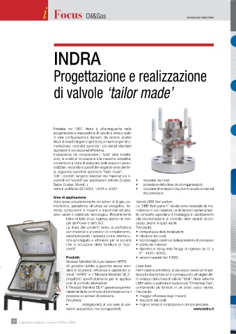
Indra opera prevalentemente nei settori oil & gas, pe- Valvola DBB Twin pattern
N
O
, T
L
D
Y F
G
R
I
E
L
A
U
G
I
I
A
I
O
N
N
T
U
T
T
N
I
T
L
C
E
N & A
A
D V
C
N
A
I
T
N
A
O
T
I
I
D
L
U
R
, T
N
O
G
N & A
O
BALL & DBB SP
L
BALL & D
C
L
A
D
B V
INTEGRAL ONE PIECE FLOATING BALL & DBB VALVES
G
L
I
I
D
F
N
V
S
O
B
INSTRUMENTATION VALVES & MANIFOLDS trolchimico, piattaforme off-shore ed energetico, for- La “DBB Twin pattern” valvola viene realizzata da mo- E D V A L V BALL & DBB SPLIT B O D Y F L O A I N T I T N E G G R , T A R L O N N N N E P E N & A I L O L T R O T N A U A G E P T I N E I E L O E F A A I E P L & D L I E F G B T O I A A N A L G B N E A S G B L & D A B L B V E S A L V E S INTEGRAL ONE PIEC INTEGRAL ONE PIECE FLOATING BALL & DBB VALVESALVES & MANIFOLDS INSTRUME
L
L & D
V
A
T
R
L O
T
I
E
C
S
L
L
E
N
L
L
O
E F
L
S & M
L
V
N
A
N
E
O
S
V
I
L
A
I
T
T B
R
E
BALL & DBB SPLIT BODY FLOATING, TRUNNION & ACTUAT
E F
O
O
N
T B
A
L
F
Y F
INSTRUMENTATION VALVES & MANIFOLDS
C
B SP
T
I
D
A
B
V
E F
A
I
T
D V
I
I
B V
E
A
R
V
T
MEN
T
S
T
O
N
C
T
D V
G B
A
A
A
E
B
T
E
NS
MEN
E
I
T
BALL & DBB SPLIT BODY FLOATING, TRUNNION & ACTUATED VALVESBALL & DBB SPLIT BODY FLOATING, TRUNNION & ACTUATED VALVES
NS
R
U
N V
MEN
O
T
B
A
E P
I
O
S
L
T
L
A
N
T
O
N
V
N V
A
S & M
U
I
U
L
F
NS
A
A
T
U
R
T
V
I
N V
I
S & M
S
A
E
G B
T
E
N V
A
O
E
O
O
S
BALL & DBB SPLIT BODY FLOATING, TRUNNION & ACTUATED VALVESL & DBB VALVES
I
L
T
S
A
NS
E
R
B V
U
L
MEN
A
L
I
E
U
C
V
L & D
T
C
S
C
S
CONNECTIONS
CONNECTIONS nendo componenti in impianti e macchinari ad altis- noblocco in vari materiali. Le dimensioni estremamen- • ASME Class – 150lb to 2500lb CON CONNECTIONS CONNECTIONS CONNECTIONS CONNE CONON CONNECTIONS CONNECTIONS CONNECTIONS CONNECTIONS CONNECTIONS • ASME Class – 150lb to 2500lb
I
E
I
T
N
ON
CONNECTIONS
• ASME Class – 150lb to 2500lb
T
C
ON
• ASME Class – 150lb to 2500lb
S
E
• ASME Class – 150lb to 2500lb
• ASME Class – 150lb to 2500lb
• ASME Class – 150lb to 2500lb
N
I
• ASME Class – 150lb to 2500lb CONNECTIONSCONNECTIONS
From 1
From 1 /8” to 2” From 1/2” to 8” • API 3000/5000 • API 3000 / • API 3000/5000/10000 • API 3000/5000/10000 • API 3000/5000/10000 From 1/2” to 8” From 1/2” to 8” From 1/2” to 8” From 1 /8” to 2” From 1 /8” to 2” From 1 /8” to 2”/8” to 2” From 1 /8” to 2” From 1 /8” to 2” From 1 /8” to 2” From 1/2” to 8” • API 3000/5000/10000
5000
From 1/2” to 8”
• API 3000
10000
From 1/2” to 8”
From 1/2” to 8”
/
10000
/
/
/
10000
5000
• API 3000/5000/10000
, BW
NPT, BSPP, BSPT, BW, SW
NPT, BSPP , BSPT, BW, SW simo valore e contenuto tecnologico. Recentemente te compatte agevolano il montaggio in abbinamento • Size – 1/2” to 8” (FB & RB) • Size – 1/2” to 8” (FB & RB) Threaded Threaded Threaded Off-Shore NPT, BSPP NPT, BSPP , BSPT , BW , SW NPT, BSPP, BSPT, BW, SW NPT, BSPP, BSPT, BW, SW NPT, BSPP , BSPT, BW, SW Threaded • Size – 1/2” to 8” (FB & RB)
, SW
, SW
NPT, BSPP, BSPT, BW
, BSPT
• Size – 1/2” to 8” (FB & RB)
• Size – 1/2” to 8” (FB & RB)
• Size – 1/2” to 8” (FB & RB)
Threaded
• Size – 1/2” to 8” (FB & RB)
• Size – 1/2” to 8” (FB & RB)
Threaded
Threaded
Threaded
Flanged
• Soft Seated & Metal Seated
• Soft Seated & Metal Seated
• Soft Seated & Metal Seated
• Soft Seated & Metal Seated
• Soft Seated & Metal Seated
G
RATING Indra ha fatto il suo ingresso anche nei mer- alla strumentazione di controllo delle variabili di pro- • Soft Seated & Metal Seated • Soft Seated & Metal Seated FlangedFlanged Flanged Flanged Petrochemical Flanged Flanged RATING RATING RATIN RATING Energy LNG RATING RATING RATING Flanged Welded (BW or SW) • Soft Seated & Metal Seated • Lever, Gearbox or Actuated
• Lever, Gearbox or Actuated
• Lever, Gearbox or Actuated
• Lever
, Gearbox or Actuated
• Lever, Gearbox or Actuated
• Lever, Gearbox or Actuated
Oil & Gas Welded (BW or SW)Welded (BW or SW)Welded (BW or SW)elded (BW or SW)
W
• Lever, Gearbox or Actuated
Welded (BW or SW)
Welded (BW or SW)
Welded (BW or SW)
• Lever, Gearbox or Actuated
6.000 - 10.000 PSI (thr
6.000 - 10.000 PSI (threaded types)
6.000 - 10.000 PSI (threaded types) Hub • Temperature Range -46°C to +240°C e Range -46°C to +240°C • Temperature Range -46°C to +240°C Hub Hub Platforms 6.000 - 10.000 PSI (thr eaded types) 6.000 - 10.000 PSI (threaded types) 6.000 - 10.000 PSI (threaded types) Hub • Temperature Range -46°C to +240°C
6.000 - 10.000 PSI (thr
eaded types)
6.000 - 10.000 PSI (threaded types)
eaded types)
• Temperatur
e Range -46°C to +240°C
• Temperature Range -46°C to +240°C
• Temperatur
• Temperature Range -46°C to +240°C HubHubHub
Hub
• Temperature Range -46°C to +240°C
SCH. 40, 80, 160, XXS (BW-SW version)
SCH. 40, 80, 160, XXS (BW-SW version)
SCH. 40, 80, 160, XXS (BW-SW version) cati del Power e dell’LNG. cesso, anche in spazi ridotti. • High Temperature on demand SCH. 40, 80, 160, XXS (BW-SW version) SCH. 40, 80, 160, XXS (BW-SW version) SCH. 40, 80, 160, XXS (BW-SW version) • High Temperature on demand
SCH. 40, 80, 160, XXS (BW-SW version)
SCH. 40, 80, 160, XXS (BW-SW version)
• High Temperatur
emperatur
• High Temperature on demand
• High Te on demand
• High Temperatur
e on demand
• High Temperature on demand
e on demand
• High Temperature on demand
e on demand
• Low Temperature on demandRATING RATING
• Low Temperatur
G
e on demand
• Low Temperature on demand
RATIN
• Low Temperatur
RATING
emperatur
N
BONNET La linea dei prodotti Indra si perfeziona Peculiarità: • Low Te on demand • Low Temperature on demand • Low Temperature on demand ASME Class – 150lb to 2500lb RATING RATING RATING BON BONNET BONNET BONNET BONNET RATING ASME Class – 150lb to 2500lb • Low Temperature on demand
ASME Class – 150lb to 2500lb BONNET BONNET
E
T
ASME Class – 150lb to 2500lb
ASME Class – 150lb to 2500lb
ASME Class – 150lb to 2500lb
ASME Class – 150lb to 2500lb
ASME Class – 150lb to 2500lb
Screwed, O.S.&Y. Bolted, Antitamper,
Screwed, O.S.&Y. Bolted, Antitamper, API 3000/5000/10000/15000 API 3000/5000/10000 / API 3000 / 10000 / / 15000 / 15000 API 3000/5000/10000/15000 API 3000/5000/10000/15000 Screwed, O.S.&Y. Bolted, Antitamper, Screwed, O.S.&Y. Bolted, Antitamper, . Bolted, Antitamper , Screwed, O.S.&Y. Bolted, Antitamper , Screwed, O.S.&Y. Bolted, Antitamper, API 3000/5000/10000/15000
Screwed, O.S.&Y. Bolted, Antitamper,
Screwed, O.S.&Y
API 3000/5000/10000/15000
/
5000
5000
API 300015000
/
10000
Extended Locking device, Cryogenic service
Extended Locking device, Cryogenic service con materiali e accessori di complemento, • compattezza delle installazioni; Extended Locking device, Cryogenic service Extended Locking device, Cryogenic service Extended Locking device, Cryogenic service
Extended Locking device, Cryogenic service
Extended Locking device, Cryogenic service
Extended Locking device, Cryogenic service
G
N
DESIGN
B - D
B
B
B
V
Single or Double Block with
L
L
E
MONOFLANGE VALVES – SLIM LINE SB - SBB - DB - DBB
I
Single or Double Block with
MONOFLANGE VALVES – SLIM LINE SB - SBB - DB - DBB caratterizzando l’azienda come interlocu- • riduzione dei costi; DESIGN DESIGN DESI DESIGN DESIGN DESIGN MONOFLANG MONO L V F N A S – S L E V I N M L L E V E E S L B - S I M L B - D E S B - D E S B B B - S B B - D B B - D B B MONOFLANGE VALV MONOFLANGE VALVES – SLIM LINE SB - SBB - DB - DBB MONOFLANGE VALVES – SLIM LINE SB - SBB - D DESIGN Single or Double Block with optional Bleed
B
B - D
G
Single or Double Block with
S – S
A
M L
B
B
N
I
M L
N
I
Single or Double Block with
A
B
V
L
A
B
S – S
E
B - D
O
B - S
B - D
E S
L
E V
Single or Double Block with
I
N
G
I
B - D
F
I
Single or Double Block with
A
N
N
S – S
B - S
MOLE
Single or Double Block with
optional Bleed (SB-SBB-DB-DBB)
optional Bleed (SB-SBB-DB-DBB)
optional Bleed (SB-SBB-DB-DBB)
optional Bleed (SB-SBB-DB-DBB)
optional Bleed (SB-SBB-DB-DBB)
optional Bleed (SB-SBB-DB-DBB)
optional Bleed (SB-SBB-DB-DBB)
Integral Ball Design: Soft & Metal Seat
Integral Ball Design: Soft & Metal Seat
Integral Ball Design: Soft & Metal Seat
Integral Ball Design: Soft & Metal Seat
Integral Ball Design: Soft & Metal Seat
I
T
S
C
S
ON
E
T
CONNECTIONS tore privilegiato e affidabile per le società • monitoraggio continuo della pressione di processo; Integral Ball Design: Soft & Metal Seat MILANO Integral Ball Design: Soft & Metal Seat CONNECTIONS CONNE CONON CONNECTIONS CONNECTIONS CONNECTIONS CONNECTIONS Integral Ball Design: Soft & Metal Seat
I
C
N
Inlet: 1/2” to 4” flanged
Inlet: 1/2” to 4” flanged
Inlet: 1/2” to 4” flanged che si occupano della fornitura di “pac- • scelta dei materiali; BONNET BONNE BON N BONNET BONNET BONNET Inlet: 1/2” to 4” flanged Inlet: 1/2” to 4” flanged Inlet: 1/2” to 4” flanged Inlet: 1/2” to 4” flanged Inlet: 1/2” to 4” flanged BONNET
T
T
E
BONNET
Outlet: Threaded & Flanged
Outlet: Threaded & Flanged
eaded & Flanged
Outlet: Threaded & Flanged Screwed, O.S.&Y. Bolted, Screwed, O.S.&Y Screwed, O.S.&Y. Bolted, Screwed, O.S.&Y. Bolted, Outlet: Thr Outlet: Threaded & Flanged Outlet: Threaded & Flanged Outlet: Threaded & Flanged Outlet: Threaded & Flanged Screwed, O.S.&Y. Bolted,
Magenta Screwed, O.S.&Y. Bolted, Screwed, O.S.&Y. Bolted, Screwed, O.S.&Y. Bolted, . Bolted,
Antitamper, Extended Locking device,
Antitamper
Antitamper, Extended Locking device,
Antitamper, Extended Locking device,
G
RATING chetti”. Antitamper, Extended Locking device, • diametro e rating della flangia di ingresso da ½” a Antitamper, Extended Locking device, , Extended Locking device, Antitamper, Extended Locking device, RATING RATING RATIN RATING RATING RATING RATING Antitamper, Extended Locking device,
Cryogenic service
Cryogenic service
ASME Class – 150lb to 2500lb
ASME Class – 150lb to 2500lb Cryogenic service Cryogenic service Cryogenic service Cryogenic service Cryogenic service ASME Class – 150lb to 2500lb ASME Class – 150lb to 2500lb ASME Class – 150lb to 2500lb ASME Class – 150lb to 2500lb Cryogenic service
ASME Class – 150lb to 2500lb
ASME Class – 150lb to 2500lb
5000
/
API 3000
API 3000/5000/10000
/
5000
API 3000/5000/10000 6” - #150 / #2500; API 3000/5000/10000 API 3000 / 10000 / 10000 API 3000/5000/10000 API 3000/5000/10000 API 3000/5000/10000
BON
BONNET
N
BONNET Prodotti: • versioni speciali Api 10000. Standard and special materials BONNET BONNET BONNET
T
E
T
BONNE
BONNET
Screwed, O.S.&Y. Bolted, Antitamper,
V
B
S
. Bolted, Antitamper
E
T
N D
E
C
O
I
,
O
I
V
L
N D
B V
S
S
A
E
E
V
L
B
Screwed, O.S.&Y
Screwed, O.S.&Y
S
Screwed, O.S.&Y. Bolted, Antitamper,
B V
N D
E
A
B V
B Screwed, O.S.&Y. Bolted, Antitamper,
V
L
A
T
G & I
L
C
N
I
SAMP
N
B V
A
J
B
I
C
N
N
N D
P
L
I
E
L
O
Screwed, O.S.&Y. Bolted, Antitamper, SAMPLING & INJECTION DBB VALVES SAMPLING & I N J E SAMO SAMPLING & INJECTION DBB VALVES SAMPLING & INJECT SAMPLING & INJECTION DBB VALVES . Bolted, Antitamper , Screwed, O.S.&Y. Bolted, Antitamper , Screwed, O.S.&Y. Bolted, Antitamper, SAMPLING & INJECTION DBB VALVES
J
I
G & I
T
Extended Optional locking device,
Extended Optional locking device,
Extended Optional locking device,
Extended Optional locking device, Modular Manifold SIL4 per sistemi HIPPS Extended Optional locking device, Extended Optional locking device, Extended Optional locking device, Extended Optional locking device,
Cryogenic service These DBBs are used for sampling & Injection Headquarters These DBBs are used for sampling & Injection Cryogenic service Cryogenic service Cryogenic service Cryogenic service Cryogenic service These DBBs are used for sampling & Injection
Cryogenic service
Cryogenic service
These DBBs are used for sampling & Injection
These DBBs ar
These DBBs are used for sampling & Injection
e used for sampling & Injection
These DBBs are used for sampling & Injection
e used for sampling & Injection
These DBBs ar
Un prodotto adatto a garantire elevati stan- Linea Iblok purpose and for further analysis of the pr ocess. ocess. ocess. SS 316/316L Nace A105 Hastelloy C276 purpose and for further analysis of the process.
ocess.
purpose and for further analysis of the pr
purpose and for further analysis of the process.
purpose and for further analysis of the process.
purpose and for further analysis of the pr
purpose and for further analysis of the pr
purpose and for further analysis of the process.
G
U
Valves are designed with Integral Body and CUSTOMIZED CONFIGURATIONCUSTOMIZED CONFIGURATIONCUSTOMIZED CONFIGURATIONCUSTOMIZED CONFIGURATION
N
O
I
R
CUSTOMIZED CONFIGURATION Valves are designed with Integral Body and Valves are designed with Integral Body and Valves are designed with Integral Body and CUSTOMIZED CONF I CUSTOMIZED CONFIGURATION CUSTOMIZED CONFIGURATION Valves are designed with Integral Body and
T
A
Valves are designed with Integral Body and
Valves are designed with Integral Body and
e designed with Integral Body and
Valves ar
dard di sicurezza, efficienza e qualità nei si- Nell’industria petrolifera, la sicurezza riveste un’impor- Integral Sampling Pr Integral Sampling Pr obe (Not W elded). elded). Duplex F51 Integral Sampling Probe (Not Welded). Titanium Integral Sampling Probe (Not Welded).
LF2
Integral Sampling Pr
obe (Not W
Integral Sampling Probe (Not W
Integral Sampling Probe (Not Welded).
elded).
obe (Not W
elded).
Integral Sampling Probe (Not Welded).
Probe length is defined in acc. to the application
Probe length is defined in acc. to the application
Probe length is defined in acc. to the application
Probe length is defined in acc. to the application
Probe length is defined in acc. to the application
Probe length is defined in acc. to the application
stemi “HIPPS” è il “Modular Manifold SIL4”, tanza fondamentale ed è il presupposto all’origine del- 4000 sqm Probe length is defined in acc. to the application Probe length is defined in acc. to the application requirements and the pipeline diameter - upon
requirements and the pipeline diameter - upon
requirements and the pipeline diameter - upon
requirements and the pipeline diameter - upon
requirements and the pipeline diameter - upon
requirements and the pipeline diameter - upon
ements and the pipeline diameter - upon
requir
requirements and the pipeline diameter - upon
ake Fr
indication. Indra can supply W
indication. Indra can supply W
indication. Indra can supply Wake Frequency
indication. Indra can supply Wake Frequency
indication. Indra can supply W
indication. Indra can supply Wake Frequency
ake Fr
equency
ake Fr
equency
indication. Indra can supply W
ake Fr
progettato specificatamente per le applica- lo sviluppo della linea di valvole “Iblok”. Nella versione of which 3000 sqm obe Length and equency SuperDuplex equency Monel 6MO indication. Indra can supply Wake Frequency and Bending Stress Calculations to ensure the correct selection of the Probe L
ess Calculations to ensur
e
and Bending Stress Calculations to ensure
e
and Bending Str
ess Calculations to ensur
and Bending Stress Calculations to ensure
and Bending Stress Calculations to ensur
e
and Bending Str
and Bending Stress Calculations to ensure
e
and Bending Stress Calculations to ensur
obe Length and
the corrobe Length and
the correct selection of the Pr
the correct selection of the Probe Length and
the correct selection of the Probe Length and
the correct selection of the Probe Length and
ect selection of the Pr
the correct selection of the Pr
the correct selection of the Probe Length and
Alloy 625/825
zioni di controllo strumentali. the valve optimum performance in time. DBB vanno a sostituire il tradizionale “Christmas Tree”, the valve optimum performance in time. F53/F55 the valve optimum performance in time. Others on demand the valve optimum performance in time.
the valve optimum performance in time.
the valve optimum performance in time.
the valve optimum performance in time.
the valve optimum performance in time.
Il “Modular Manifold SIL4” garantisce perma- combinando più funzioni in un unico corpo valvola. rev.0 - 2020 of production area
nentemente la continuità di informazione tra il Peculiarità:
processo e i sensori di pressione. • maggior efficienza degli impianti;
re
1 100% Pressure Testing
u
0
s
s
re
0
%
0
3D Checking
P
”
P
%
u
e
s
re
100% Pressure Testing Bunker “High Pressure Test” NDT Testing Peculiarità: • riduzione dei costi; i n g Manufacturing Manufacturi Manu Man Manufacturing Engineeringuring Engineering Manufacturing Manufacturing 3D Ch e c k i n g NDT Testing NDT Te s t NDT Testinger “ 3D CheckingBunker “High Pressure Test” Bunker “High Pressure Test” Bunker “High Pressure Test” High Pressure Test” 100 NDT Testing 100% s s 0 P u % re P s T s re B re t s in n T re s T t i
3D Checking 3D Checking
u
u
g
e
s
s
s
e
s
P
0
T
%
t
NDT Testingker “High Press
g
re
in
re
10
Engineering
Bunker “ High Pressure Test”
3D Checking
Engineering
100% Pressure Testing
Te
n
t
i
a
r
c
ng
i
g
B
n
n
k
u
i
u
r
Engineering
t
s
g
f
s
n
i
e
g
n
Engineering
e
Engi
Engin
r
t
e
u
t
c
e T
1
u
a
ng
r
e
f
e
NDT NDT Testing
g
s
re
1
Manufacturing 3D Checking3D Checking
u
t
in
T
e
• obbligatorietà di una serie di ope- • migliori tempi di installazione e di manutenzione.
razioni sequenziali, mai sovrapponibili; www.indra.it
74 74 Impiantistica Italiana - Gennaio-Febbraio 2021 EN ISO 15848-2 EN ISO 15848-1 Fugitive Emission ISO 10497–API 607–API 6FA Fire Safe the valve optimum performance in time. the correct selection of the Probe Length and and Bending Stress Calculations to ensure indication. Indra can supply Wake Frequency requirements and the pipeline diameter - upon Probe length is defined in acc. to the application Integral Sampling Probe (Not Welded). Valve
”
t
P
re
NDT Testing
s
k
t
Engineering
f
i
s
re
ng
0
t
3D Checking
0
c
re
1
i
u
a
Engineering
Engineeringuring
a
e
r
e
t
n
c
g
n
Manu
ng
Manufacturi
u
f
n
i
g
r
s
Manufacturing 3D Checking3D Checking
NDT Testing 100%
e
r
g
n
3D Checking
%
u
u
i
t
g
100
e T
in
Engi
Bunker “High Pressure Test” 00% Pressure Testing
t
s
100% Pressure Testing
P
s
re
T
s
s
i
n
g
re
re
NDT Testinger “
in
u
u
NDT
s
T
e
e
re
g
s
re
e
B
in
n
e T
s
t
g
k
n
in
s
NDT Testingker “High Press
g
s
10
3D CheckingBunker “High Pressure Test” Bunker “High Pressure Test” Bunker “High Pressure Test” High Pressure Test”
in
Manufacturing
NDT Testing
re
u
B
%
t
e
Bunker “High Pressure Test”
r
Te
NDT Te
g
s
P
0
s
”
T
s
u
the valve optimum performance in time.
the valve optimum performance in time.
the valve optimum performance in time.
the valve optimum performance in time.
the valve optimum performance in time.
the corrobe Length and
the correct selection of the Probe Length and
the correct selection of the Pr
the correct selection of the Probe Length and
obe Length and
the correct selection of the Probe Length and
the correct selection of the Pr
obe Length and
ect selection of the Pr
e
e
and Bending Stress Calculations to ensure
and Bending Str
ess Calculations to ensur
e
and Bending Stress Calculations to ensur
and Bending Stress Calculations to ensure
and Bending Stress Calculations to ensur
and Bending Str
ess Calculations to ensur
ake Fr
equency
indication. Indra can supply Wake Frequency
indication. Indra can supply Wake Frequency
equency
indication. Indra can supply W
ake Fr
equency
indication. Indra can supply W
indication. Indra can supply W
equency
ake Fr
indication. Indra can supply W
requirements and the pipeline diameter - upon
requirements and the pipeline diameter - upon
requirements and the pipeline diameter - upon
requir
ements and the pipeline diameter - upon
requirements and the pipeline diameter - upon
requirements and the pipeline diameter - upon
Probe length is defined in acc. to the application
Probe length is defined in acc. to the application
Probe length is defined in acc. to the application
Probe length is defined in acc. to the application
Probe length is defined in acc. to the application
Probe length is defined in acc. to the application
Integral Sampling Probe (Not Welded).
Integral Sampling Probe (Not W
Integral Sampling Pr
Integral Sampling Pr
elded).
elded).
obe (Not W
Integral Sampling Probe (Not Welded).
obe (Not W
elded).
elded).
Integral Sampling Pr
obe (Not W
e designed with Integral Body and
Valves are designed with Integral Body and
Valves ar
Valves are designed with Integral Body and
Valves are designed with Integral Body and
Valves are designed with Integral Body and
G
I
CUSTOMIZED CONF
A
U
CUSTOMIZED CONFIGURATION
R
Valves are designed with Integral Body and CUSTOMIZED CONFIGURATIONCUSTOMIZED CONFIGURATIONCUSTOMIZED CONFIGURATIONCUSTOMIZED CONFIGURATION
O
T
N
I
purpose and for further analysis of the process.
purpose and for further analysis of the process.
purpose and for further analysis of the pr
ocess.
ocess.
purpose and for further analysis of the pr
purpose and for further analysis of the pr
purpose and for further analysis of the pr
These DBBs are used for sampling & Injection
e used for sampling & Injection
These DBBs are used for sampling & Injection
These DBBs are used for sampling & Injection
These DBBs ar
These DBBs ar
e used for sampling & Injection
These DBBs are used for sampling & Injection
Cryogenic service
Cryogenic service
Cryogenic service
Cryogenic service
Cryogenic service
Cryogenic service
Extended Optional locking device,
Extended Optional locking device,
Extended Optional locking device,
Extended Optional locking device,
Extended Optional locking device,
Extended Optional locking device,
Extended Optional locking device,
,
,
Screwed, O.S.&Y. Bolted, Antitamper,
. Bolted, Antitamper
Screwed, O.S.&Y
Screwed, O.S.&Y. Bolted, Antitamper,
,
Screwed, O.S.&Y
. Bolted, Antitamper
B Screwed, O.S.&Y. Bolted, Antitamper,
Screwed, O.S.&Y. Bolted, Antitamper,
Screwed, O.S.&Y. Bolted, Antitamper
L
E
I
J
O
N
V
O
J
B V
J
SAMP
B V
B V
SAMPLING & INJECTION DBB VALVES
L
I
SAMO
V
E
E
S
L
N
A
P
S
N
G & I
C
N
SAMPLING & INJECT
SAMPLING & INJECTION DBB VALVES
C
I
B
I
T
G & I
N D
SAMPLING & I
A
T
E
I
B
B
O
N
N D
C
A
L
E
T
I
N D
E
BONNET
T
BONNE
N
BON
BONNET
BONNET
BONNET
BONNET
T
API 3000
/
/
API 3000/5000/10000
API 3000/5000/10000
10000
API 3000
10000
/
5000
/
API 3000/5000/10000
API 3000/5000/10000
API 3000/5000/10000
ASME Class – 150lb to 2500lb
ASME Class – 150lb to 2500lb
ASME Class – 150lb to 2500lb
ASME Class – 150lb to 2500lb
ASME Class – 150lb to 2500lb
ASME Class – 150lb to 2500lb
ASME Class – 150lb to 2500lb
Cryogenic service
Cryogenic service
Cryogenic service
Cryogenic service
Cryogenic service
Cryogenic service
RATING
RATIN
RATING
RATING
RATING
RATING
RATING
Antitamper
, Extended Locking device,
Antitamper, Extended Locking device,
Antitamper, Extended Locking device,
Antitamper, Extended Locking device,
Antitamper, Extended Locking device,
Antitamper, Extended Locking device,
Screwed, O.S.&Y. Bolted,
Screwed, O.S.&Y. Bolted,
Screwed, O.S.&Y. Bolted,
Screwed, O.S.&Y
. Bolted,
Screwed, O.S.&Y
Screwed, O.S.&Y. Bolted,
. Bolted,
eaded & Flanged
Outlet: Threaded & Flanged
Outlet: Threaded & Flanged
Outlet: Threaded & Flanged
Outlet: Threaded & Flanged
Outlet: Threaded & Flanged
Outlet: Thr
Outlet: Threaded & Flanged
N
BONNET
BONNE
BONNET
BON
BONNET
T
E
T
BONNET
Inlet: 1/2” to 4” flanged
Inlet: 1/2” to 4” flanged
Inlet: 1/2” to 4” flanged
Inlet: 1/2” to 4” flanged
Inlet: 1/2” to 4” flanged
Inlet: 1/2” to 4” flanged
Inlet: 1/2” to 4” flanged
S
I
CONNECTIONS
ON
CONNECTIONS
T
C
CONON
CONNECTIONS
I
CONNECTIONS
CONNECTIONS
S
C
N
CONNE
Integral Ball Design: Soft & Metal Seat
Integral Ball Design: Soft & Metal Seat
Integral Ball Design: Soft & Metal Seat
Integral Ball Design: Soft & Metal Seat
Integral Ball Design: Soft & Metal Seat
Integral Ball Design: Soft & Metal Seat
optional Bleed (SB-SBB-DB-DBB)
optional Bleed (SB-SBB-DB-DBB)
optional Bleed (SB-SBB-DB-DBB)
optional Bleed (SB-SBB-DB-DBB)
optional Bleed (SB-SBB-DB-DBB)
optional Bleed (SB-SBB-DB-DBB)
Single or Double Block with
Single or Double Block with
Single or Double Block with
Single or Double Block with
Single or Double Block with
Single or Double Block with
L
N
I
MOLE
L
I
B
B - D
V
B - D
E S
F
E S
B - D
B
B - D
E S
MONOFLANGE VALVES – SLIM LINE SB - SBB - DB - DBB
MONOFLANGE VALV
B - S
B
B
A
B
B
B - D
B - S
B - D
E V
MONO
M L
N
I
A
M L
A
L
L
S – S
L
S – S
E
E S
A
E V
E
I
V
E V
I
S – S
O
N
N
B
A
MONOFLANGE VALVES – SLIM LINE SB - SBB - DB - DBB
S – S
B - S
E
L
V
G
F
L
MONOFLANGE VALVES – SLIM LINE SB - SBB - DB - DBB
B - D
I
MONOFLANG
N
I
B - D
L
M L
DESIGN
G
DESIGN
DESI
DESIGN
DESIGN
DESIGN
N
Extended Locking device, Cryogenic service
Extended Locking device, Cryogenic service
Extended Locking device, Cryogenic service
Extended Locking device, Cryogenic service
Extended Locking device, Cryogenic service
Extended Locking device, Cryogenic service
Extended Locking device, Cryogenic service
/
15000
API 3000
/
API 300015000
/
15000
/
10000
/
API 3000/5000/10000
/
API 3000/5000/10000/15000
API 3000/5000/10000/15000
5000
5000
10000
/
Screwed, O.S.&Y. Bolted, Antitamper,
API 3000/5000/10000/15000 Screwed, O.S.&Y. Bolted, Antitamper, Screwed, O.S.&Y. Bolted, Antitamper,
,
Screwed, O.S.&Y. Bolted, Antitamper
. Bolted, Antitamper
,
Screwed, O.S.&Y. Bolted, Antitamper,
Screwed, O.S.&Y
Screwed, O.S.&Y. Bolted, Antitamper,
ASME Class – 150lb to 2500lb
ASME Class – 150lb to 2500lb
ASME Class – 150lb to 2500lb
ASME Class – 150lb to 2500lb
ASME Class – 150lb to 2500lb
BONNET
N
ASME Class – 150lb to 2500lb BONNET BONNET
T
BONNET
BONNET
BONNET
BON
e on demand
• Low Temperature on demand
• Low Te on demand
• Low Temperatur
• Low Temperature on demand
RATING
e on demand
RATING
• Low Temperatur
emperatur
• Low Temperature on demandRATING RATING
RATIN
RATING
• Low Temperature on demand
G
• High Temperatur
e on demand
• High Temperature on demand
• High Temperatur
emperatur
e on demand
• High Temperature on demand
• High Temperature on demand
• High Temperature on demand
• High Te on demand
SCH. 40, 80, 160, XXS (BW-SW version)
SCH. 40, 80, 160, XXS (BW-SW version)
SCH. 40, 80, 160, XXS (BW-SW version)
SCH. 40, 80, 160, XXS (BW-SW version)
SCH. 40, 80, 160, XXS (BW-SW version)
SCH. 40, 80, 160, XXS (BW-SW version)
SCH. 40, 80, 160, XXS (BW-SW version)
• Temperatur
• Temperature Range -46°C to +240°C
• Temperature Range -46°C to +240°C
e Range -46°C to +240°C
• Temperature Range -46°C to +240°C HubHubHub
• Temperatur
• Temperature Range -46°C to +240°C
Hub
Hub
• Temperature Range -46°C to +240°C
e Range -46°C to +240°C
Hub
6.000 - 10.000 PSI (threaded types)
6.000 - 10.000 PSI (threaded types)
6.000 - 10.000 PSI (thr
eaded types)
6.000 - 10.000 PSI (threaded types)
6.000 - 10.000 PSI (thr
eaded types)
6.000 - 10.000 PSI (thr
eaded types)
6.000 - 10.000 PSI (threaded types)
• Lever, Gearbox or Actuated
Welded (BW or SW)
Welded (BW or SW)
, Gearbox or Actuated
• Lever, Gearbox or Actuated
• Lever, Gearbox or Actuated
• Lever
Welded (BW or SW)
Welded (BW or SW)
• Lever, Gearbox or Actuated
Welded (BW or SW)
Welded (BW or SW)
• Lever, Gearbox or Actuated
• Lever, Gearbox or Actuated
RATING
RATING
RATING
RATIN
RATING
RATING
RATING
• Soft Seated & Metal Seated
Flanged
• Soft Seated & Metal Seated
Flanged
• Soft Seated & Metal Seated
• Soft Seated & Metal Seated
• Soft Seated & Metal Seated
Flanged
• Soft Seated & Metal Seated FlangedFlanged
• Soft Seated & Metal Seated
Flanged
• Size – 1/2” to 8” (FB & RB)
• Size – 1/2” to 8” (FB & RB)
Threaded
• Size – 1/2” to 8” (FB & RB)
• Size – 1/2” to 8” (FB & RB)
Threaded
• Size – 1/2” to 8” (FB & RB)
Threaded
• Size – 1/2” to 8” (FB & RB)
Threaded
• Size – 1/2” to 8” (FB & RB)
Threaded
Threaded
NPT, BSPP
, BW
NPT, BSPP , BSPT, BW, SW
NPT, BSPP, BSPT, BW, SW
, BSPT
NPT, BSPP
, SW
, BSPT
NPT, BSPP, BSPT, BW
NPT, BSPP, BSPT, BW, SW
NPT, BSPP, BSPT, BW, SW
, SW
, SW
/
From 1/2” to 8”
• API 3000/5000/10000
5000
10000
10000
/
/
• API 3000/5000/10000
5000
• API 3000/5000/10000
• API 3000/5000/10000
• API 3000/5000
From 1/2” to 8”
From 1/2” to 8”
• API 3000
• API 3000
From 1/2” to 8”
10000
/
From 1/2” to 8”
From 1 /8” to 2”
From 1 /8” to 2”/8” to 2”
From 1 /8” to 2”
From 1 /8” to 2”
From 1/2” to 8” From 1 /8” to 2”
From 1 /8” to 2”
From 1
• ASME Class – 150lb to 2500lb
I
• ASME Class – 150lb to 2500lb
E
N
• ASME Class – 150lb to 2500lb
S
• ASME Class – 150lb to 2500lb
CONNECTIONS
C
• ASME Class – 150lb to 2500lb CONNECTIONSCONNECTIONS
CONNECTIONS
ON
T
• ASME Class – 150lb to 2500lb
• ASME Class – 150lb to 2500lb
CONNECTIONS
CON
E
CONNE
S
ON
S
CONNECTIONS
CONON
N
CONNECTIONS
I
CONNECTIONS
C
I
CONNECTIONS
CONNECTIONS
T
C
S & M
E
S
T
N
E
I
T
E
N
S
D V
E
A
N
O
A
BALL & DBB SPLIT B
O
A
O
T
E
I
MEN
V
L
INTEGRAL ONE PIECE FLOATING BALL & DBB VALVESALVES & MANIFOLDS
T
E
I
A
L & D
I
V
V
L
D V
F
O
O
C
T
INTEGRAL ONE PIEC
L O
INSTRUMENTATION VALVES & MANIFOLDS
G
E F
V
L
A
N V
A
I
F
L
T
I
E P
I
L
A
INSTRUMENTATION VALVES & MANIFOLDS
L & D
O
S
V
N
G
E
L
L
L
E F
G
S
L
O
BALL & DBB SP
C
D
C
L O
I
N & A
S
V
I
O
R
A
A
L
O
INSTRUMENTATION V
I
O
A
N
E
S
N
T
D
E P
L
C
L
B V
E F
E
A
A
L
B
B V
I
T
L
S
, T
I
N
U
, T
I
L
V
I
L
E
A
T
S
T B
L
T
A
A
E
U
N V
V
D V
D V
D
L
E F
A
T
N
I
A
A
O
D
E
BALL & DBB SPLIT BODY FLOATING, TRUNNION & ACTUAT
L
I
BALL & D
F
L
N
E
I
N
S
E P
L
O
S & M
G B
I
E
Y F
B
O
N
T
B SP
L O
A
V
MEN
N V
I
L
N
E
L & D
R
B V
D
A
T
L
T
T
G B
A
I
MEN
T
T
U
T
T
A
Y F
NS
E
R
A
I
E
I
A
T
S
G
E P
G
N
S
E F
U
R
A
T
O
BALL & DBB SPLIT BODY FLOATING, TRUNNION & ACTUATED VALVESL & DBB VALVES
L
A
A
N
U
NS
I
V
N
I
L
S
I
E
N
O
R
E
R
I
G B
A
E
NS
B V
T
B
A
U
T
I
T
S & M
O
T
L
R
I
S & M
C
, T
U
N
N
E
I
BALL & DBB SPLIT BODY FLOATING, TRUNNION & ACTUATED VALVESBALL & DBB SPLIT BODY FLOATING, TRUNNION & ACTUATED VALVES
Others on demand
Others on demand
Others on demand
Others on demand
Others on demand
Others on demand
For Eu
s
r
o
6MO,
r
i
6MO,
For EAC Countries
6MO,
6MO,
e
t
6MO,
i
t
A
For EAC Countries
n
n
e
C C
6MO,
u
6MO,
For EAC Countrie
s
s
For EAC Countries
6MO,
sok
E
B1
ASME B16.10
sok
ASME B16.10
ASME B16.10
Norsok
6
Norsok
.
N
10
ASME B16.10
ASM10
or
ASME B16.10 Norsok
ASME B1
N
or
.
Norsok
6
Norsok
EAC-CU-TR 032/2013
a
a
t
R
t
o
Titanium,
l
CU
EAC-CU-TR 032/2013
Titanium,
T
t
EAC-CU-TR
eme
-
n
g
03
n
Titanium,
n
t
Environmental M
a
EAC-CU-TR 032/2013
a
g
Environmental Management
/
a
n
Environmental Manageme
n
a
n
EAC-
n
M
2
a
g
Titanium,
Titanium,
Titanium,
Envirnt
Environmental Management2013EAC-CU-TR 032/2013 032/2013
eme
EAC-CU-TR 032/2013
me
Titanium,
me
l
Titanium,
a
n
M
3
UNI EN ISO 14001:2015
UNI EN I
V
UNI EO 1
R 0
UNI EN ISO 14001:2015
E M
1
0
1
8
R 0
0
NACE M
A
ASME VIII
NACE MR 01-75 / MR 01-03Alloy 625/Incoloy 825, C-276,
2
0
ASME VIIIR 01-75 / MR 01-03
5
3
O 1
M
III
NACE M
O 1
Alloy 625/Incoloy 825, C-276,
1
UNI EN ISO 14001:2015
Alloy 625/Incoloy 825, C-276,
7
ASM
S
5
Alloy 625/Incoloy 825, C-276,
4
C
ASME V
EN ISO 1
7
5 / M
0
ASME VIII
5 / M
5
7
E
0
III
Alloy 625/Incoloy 825, C-276,
0
1
R 0
ASME VIII-75 / MR 01-03
-
R 0
1
EN ISO 15848-2
0
R 0
A
:
5
-
EN ISO 15848-2
8
UNI EN ISO 14001:2015
8
1
2
-
-
Alloy 625/Incoloy 825, C-276,
2
1
:
NACE MR 01-75 / MR 01-03Alloy 625/Incoloy 825, C-276,
S
N
E M
EN ISO 15848-2
2
1
E
0
NACE MR 01-75 / MR 01-03
N
:
UNI EN ISO 1400
E M
C
N
5 / M
4
C
R 0
1
N I
III
A
EN ISO 15848-2
1
4
5
A
-
Alloy 625/Incoloy 825, C-276,
V
1
r C
t
N f
a
8
EN ISO 15848-1
5
-
R
n
Monel,
EN ISO 15848-1or EAC Countries
EN ISO 15848-1a
e
Monel,
o
EN ISO 1
For EAC C
s
a
CRN for Canada
s
r C
For EAC Countries
N f
r C
For Eu
8
o
o
5
C C
EN ISO 15848-1 For EAC Countries
F
C
u
o
EN IS
r
a
Monel,
Monel,
N f
1
i
Monel,
n
o
O 1
n
8
Monel,
t
CRN f
a
For EAC Countriesnada
r C
d
R
C
n
Monel,
i
CRN for Canada Monel,
e
r
A
4
For EAC Countriesanada
2
ASME/ANSI B16.5
A
I 6
ASME/ANSI B16.5I 602
A
5
2
API 602
ASMEI 6
.
E ASME/ANSI B16.56.5
NS
ASME/ANSI B16.5
I
API 6
API 602
ASME/ANSI B16.5
1
ASME/ANSI B1
A
P
0
0
2
P
0
B
API 602
/
API 602
A
s
A105, LF2,
i
A105, LF2,
n
Fugitive Emission
g
2
A
n
n
s
A105, LF2,
E
A105, LF2,
t
t
eme
Health & Safety Management011EAC-CU-TR 012/2011 012/2011
Fugitive Emission
io
/
a
n
y
Health & Safety Management
s
01
Fugit Emi
a
t
A105, LF2,
2
g
EAC-CU-TR 012/2011
f
Health & Safety Manageme
n
n
-
U
e
Health & Safety M
R
f
e
Fugitive EmissionC-CU-TR
t
EAC-CU-TR 012/2011
&
C
a
n
t
A105, LF2,
a
Sa
a
EAC-CU-TR 012/2011
A105, LF2,
n
Fugitive EmissionAC-CU-TR 012/2011
Emi
n
EAC-
g
Fugitive
T
y
M
Health & Safety Management
s
M
A105, LF2,
v
eme
Health
Health &eme
a
S
0
G
A
0
A
R
E
S
E
1
BS OHSAS 18001:2007
ATEX 20
BS OHS
:
O
A
F53/F55,
BS OS 1
4
0
S
0
7
2
I
T
BS OHSAS 18001
8
UL
1
F53/F55,
U
REGULATIONS
4
A
GU
BS OHSAS 18001:2007
H
7
ATEX 2014/34/EUONS
ATEX/3
0
/3
4
REGU
ATEX 2014/34/EUTIONS F53/F55,
I
O
8
F53/F55,
T
0
0
R
7
REGULA
0
F53/F55,
ATEX 2014/34/EU
REGULATIONS
0
2
BS OHSAS 18001:2007 ATEX 2014/34/EU
BS OHSAS 18001:2007
1
F53/F55,
:
4
:
N
2
F53/F55,
E
L
REGULATIONS
T
F53/F55,
S 1
0
.
ASME/ANSI B1.20.1
ASME/ANSI B1.20.1
6D
NS
ASME/ANSI B1.20.1 API 6D
I
/
API 6D
A
1
A
PI
6D
ASME/ANSI B
B
A
6D
1
API 6D
PI
API 6D
.
A
.
20
1
ASME
API 6D
1
ASME/ANSI B1.20.1
Duplex F51, SuperDuplex
Duplex F51, SuperDuplex
Duplex F51, SuperDuplex
Duplex F51, SuperDuplex
Duplex F51, SuperDuplex
NORMS &
o
u
For EAC C
A
r E
C C
F
t
r E
CERTIFICATIONS
n
For Eu
FoC C
A
I 6
P
0
P
0
–
A
A
o
A
F
7
F
–
r
i
e
t
e
n
s
N
4
O
0
CERTIFICATIONS–API 607–API 6FAMS &
I
S
o
s
u
A
r
i
e
r
i
u
o
C C
n
t
7
O
N
S
TI
C
A
S
A
CERTIFICATIONS
TI
C
CERTIFICATIONS
CERTIFI
CERTI
CERTIFI
CERTI
C
CERTIFICATIONS
Duplex F51, SuperDuplex
NORMS &
For EAC Countries
F
N
I
O
A
TI
CERTIFICATIONS
7
–
ISO 104
9
0
4
S
ISO 10497–API 607–API 6FAtries
0
P
7
CERTIFICATIONS
ISO 1A
9
I
C
S
N
CERTIFICATIONSAPI 607–API 6FA
O
F
O 1
O
N
TI
A
I
S
9
M
R
N
S &
O
O
NORMS & Duplex F51, SuperDuplex
O
R
N
ISO 10497–API 607–API 6FAuntries
C C
A
o
For EAC Countries
Duplex F51, SuperDuplex
r E
M
R
S &
o
F
N
1
:
0
0
5
2
5
8
1 PRODUCT
0
SS 316/316L,
1
0
0
S
UNI EO 9
UNI EN ISO 9001:2015
N I
SS 316/316L,
2
0
1
:
O 9
6
P
9
ER
1
8
A
T
2
API 598MATERIALS
IALS
0
PRODUCT afe
/
MA
T
PRODUC
9
PRODUC
I 5
SS 316/316L,
T
4
COMPANY
UNI EN I
COMPA
1
I
MA
MA
A
EAC-CU-TR 010/2011
AL
COMPANY
I
UNI EN ISO 9001:2015
6.34
Y
T
ER
N
S
PA
COM
AL
CONSTRUCTION
COMPANY N ISO 9001:2015
SS 316/316L,
N
PED 2014/68/EUTERIALS SS 316/316L,
SS 316/316L,
I 5
MA
MATERIALS
T
I E
9
8
MATERIALS
CONSTRUCTION
S
T
PED 2014/68/EU
ER
N
U
P
Y
ASME/ANSI B16.34
SS 316/316L,
API 598
Fi
EAC-CU-TR 010/2011/ANSI B
A
Fire Safe CONSTRUCTION CONSTRUCTION STRUCTION I B16.34
ME
A
ASME/ANSI B16.34
0
1
P
PED 2
PRODUCT Safe /68/EUCTION
/
UNI EN ISO 9001:2015 PRODUCT EAC-CU-TR 010/2011EAC-CU-TR 010/2011EAC-CU-TR 010/2011PED 2014/68/EU
ME
A
I
I 5
P
P
CONSTRUCTION
A
NS
S
A
/
2
/
6
e
U
4
8
1
4
0
E
/
1
8
Fi
P
D
6
2
E
r
D CONSTRU
CON ASME/ANS
/
0
B
.
Fire Saf
1
4
3
I 5
A
e
EAC-CU-TR 010/20118/EUERIALS
COMPANY I EN ISO 9001:2015U-TR 010/2011
4
Fire
9
P
r
e
I 5
D
SS 316/316L,
P
ASME/ANSI B16.34
E
S
A
A
9
8
ME
6
/
A
I 5
EAC-C
1
S
NS
.
1
B
U Fire Safe Safe
N
3
3
.
9
8
4
I