
Page 29 - Industrial Plants
P. 29
revamping of existing and conventional gasification
plant to upgrade its design to cope with a low-carbon
impact concept. The latter encompasses the greenfield
design flexibility required by the sustainable methanol
production to deal with the energy transition.
The revamping complexity
of the existing gasification area
One of the main challenges of the project execution is
dictated by the revamping of existing process facilities:
the old concept relies on a conventional design having
fossil fuels as feedstock. Project Air will shift to a mix of
biogas and recycled hydrocarbons and another novelty
is represented by the maximization of re-usage of
by-products and tail streams from other production
areas at Stenungsund.
The retrofit of existing facilities is approached by Wood
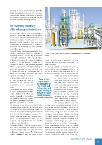
following a consolidated methodology, leveraging its Figure 3 - Side view of new structures located adjacent to the existing
engineering expertise. The first step in revamping gasifier
projects is the realisation of a field survey with the aim
to determine the status of the existing installations structure in white colour is positioned in a very
compared to the documentation provided by the congested area. Coloured adjacent structures are the
Customer. In addition to the traditional engineering newly added ones.
techniques, a laser scan is performed. What is acquired The structure is delimited on the west side by an old,
with the laser scan is then compared with the 3D model decommissioned gasifier and a piperack, while on the
to highlight any possible inconsistencies with the east side an internal access road bounds the area. On
existing technical drawings. This methodology leads to the south side, the boiler water circulation pumps are
a perfect knowledge of the actual installed, and other production facilities
conditions of the facilities in the field “Wood is fully are located farther in the same
and does not allow any margin of committed for direction. An interconnecting piperack
uncertainty in the analyses and the execution of runs to the north of the structure, with
considerations of the subsequent the Frond-end space constraining piping expansion
phases. Engineering and loops. With such a limited space
The gasification area is composed by Design, leveraging availability and the constraints of the
an existing gasifier designed to partial its technological existing concrete basements and
oxidate a feed stream of natural gas capabilities and foundations, a high revamping
possibly integrated by hydrocarbon engineering expertise complexity has been addressed by
liquids such as propane and butanol. Wood implementing a tailor-made
This gasifier is installed as a stand-by strategy based on few key concepts.
gasification equipment to a parallel The revamping solutions has been
train producing syngas further converted into other carefully reviewed optimizing the new structures both in
specialty chemicals. With Project Air, the gasifier will be terms of their locations and heights. A key element is
revamped to process liquid hydrocarbon streams from the segregation of process fluids, to avoid any possible
other units, biogas from the national gas network and it incompatibility arising from shell and tube heat
will be connected to new equipment as required by the exchangers heating oxygen, biogas and liquid
upstream feedstock feeding and preheating section hydrocarbon streams. A newly added structure to the
and by the downstream syngas cooling. A group of north side of the gasifier is designed to locate the liquid
equipment, not adequate for the new operating hydrocarbons and the biogas pre-heaters on the
conditions, is also dismantled. ground floor while on the top floor the oxygen pre-
The existing gasifier is installed in a steel structure of heating exchangers and the water coolers are installed
about twenty meters high and requires to be close (Figure 3). Such structure is limited in height due to the
coupled via a transfer line to a new waste heat boiler to interference of an existing flare piping expansion loop.
be allocated in the same structure. The plot plan detail The syngas cooling section is placed in a second new
is given in Figure 2, where the above-mentioned structure located to the south of the existing one,
INDUSTRIAL PLANTS - May 2024
27