Page 68 - index
P. 68
Fig. 3 – Structure of the • location code for classifcation of plant areas in The structure of the identifcation code is reported
identifcation code; (*) A3 structures, on foors and in rooms. in fgure 3.
is an additional code used The unit codes used for Stade COGEN project are:
only for pilot valves, multiple “0” Balance of Plant (BOP)
drives, multiple supplies Process-related code
for electric loads and “1” Cogen train #1
identifcation of measuring This classifcation splits the plant with respect “2” Cogen train #2
circuits which share one to the process-related function. This is the most “3” Cogen train #3
sensor, multiple manual important designation for engineering activities “7” Steam Turbine
take-off valves for a single since it is used by all disciplines. “9” General electrical systems
instrument The code is divided into different structuring steps Step 0 identifes the Overall Plant code: G = 1.
(referred to as breakdown levels in KKS Code) with Step 1 (Function) identifes the different systems
different meanings and level of detail, starting from and subsystem composing the unit (e.g. gas
the overall plant, through the equipment and up to turbine system).
the single component. Step 2 (Equipment Unit) identifes the different
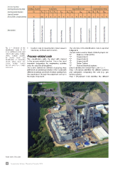
Aerial view of the plant
66 Impiantistica Italiana - Novembre-Dicembre 2013