Page 84 - Industrial Plants 2014
P. 84
solution provides optimum continuity of service as
well as simple inspection and maintenance
procedures for the motor control centre units.
The PMCC with its withdrawable units was specially
designed so that the system can constantly analyse
voltage and frequency values on the two incoming
lines. In the event of a fault on the main incoming
line, the generator starts and the breaker switches
open to provide network requirements. When power
is restored, the main
line automatically In the event of a
returns to its initial fault on the main
configuration. incoming line, the
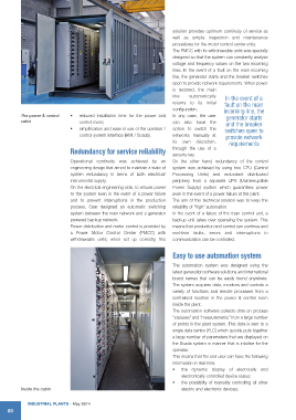
The power & control • reduced installation time for the power and In any case, the user generator starts
cabin control room; can also have the and the breaker
• simplification and ease of use of the operator / option to switch the switches open to
control system interface (HMI / Scada). networks manually at provide network
its own discretion, requirements
Redundancy for service reliability through the use of a
security key.
Operational continuity was achieved by an On the other hand, redundancy of the control
engineering design that aimed to maintain a state of system was achieved by using two CPU (Central
system redundancy in terms of both electrical/ Processing Units) and redundant distributed
instrumental supply. periphery from a separate UPS (Uninterruptible
On the electrical engineering side, to ensure power Power Supply) system which guarantees power
to the system even in the event of a power failure even in the event of a power failure at the plant.
and to prevent interruptions in the production The aim of this technical solution was to keep the
process, Cear designed an automatic switching reliability of “high” automation.
system between the main network and a generator In the event of a failure of the main control unit, a
powered backup network. backup unit takes over operating the system. This
Power distribution and motor control is provided by means that production and control can continue and
a Power Motor Control Center (PMCC) with real-time faults, errors and interruptions in
withdrawable units; when set up correctly, this communication can be controlled.
Easy to use automation system
The automation system was designed using the
latest generation software solutions and international
brand names that can be easily found anywhere.
The system acquires data, monitors and controls a
variety of functions and remote processes from a
centralised location in the power & control room
inside the plant.
The automation software collects data on process
“statuses” and “measurements” from a large number
of points in the plant system. This data is sent to a
single data centre (PLC) which quickly puts together
a large number of parameters that are displayed on
the Scada system in manner that is intuitive for the
operator.
This means that the end user can have the following
information in real-time:
• the dynamic display of electrically and
electronically controlled device status;
• the possibility of manually controlling all other
Inside the cabin electric and electronic devices;
IndustrIal Plants - May 2014
80