Page 49 - Impiantistica industriale Luglio Agosto 20147
P. 49
Table 5 - Electrochemical: fow battery
technology Physical Principle Power energy Discharge cycle life response effciency caPeX lcoe
range range time life Duration time
Flow Battery (FB) FB uses two liquid Up to 50 Up to 500 Some hours to Up to < 15 years Some 70-75% From 500 From 100 to
electrolytes separated MW MWh 10 hours 12,000 milliseconds to 1200 €/ 350 €/kWh
by a ion- selective cycles kW
membrane, stored
in separated tanks
and pumped into the
batteries when required
kilovolts) and are designed to buffer power • power capacity range;
fuctuations originating from the generation • energy range;
and the demand side. These storage facilities • discharge time;
are only the pumped hydro, and CAES; • cycle life;
• medium energy storage systems located within • life duration;
the distribution grids, near to the locations • response time;
where energy is consumed and where are • conversion effciency;
mainly connected the renewable plants; • Total Required Capital (CAPEX);
• small energy storage systems located within • Levelized Cost Of Electricity (LCOE).
building, factories and houses.
The required total capital cost is based on overnight
Consumers who charge their batteries during capital costs plus estimated project/site-specifc
off-peak hours may also sell the electricity to the costs and owner’s costs. This capital cost does
utilities or to other consumers during peak hours. not include production tax credits, investment
With high PV (PhotoVoltaic), biomass and wind tax credits, loan guarantees, or other incentive
penetration in some regions, cost-free surplus programs.
energy is sometimes available. Figure 1 indicates LCOE is including estimated capital costs. LCOE
different EES and the duration of their operation. does not include production tax credits, investment
These changes of power generation technologies tax credits, loan guarantees, or other incentive
could also have a signifcant impact on the programs. Within the above mentioned tables
electricity sector structure that will move from a we reported the main technologies that presently
verticalized to a more decentralized organization. could have applications to store power produced
by renewables plant and on grid stability.
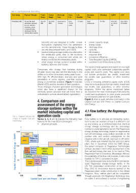
4. Comparison and Figure 2 offers a quick tentative information of the
Capital Cost per Unit Power vs Capital Cost per
assessment of the energy Unit Energy.
storage systems within the
market including capital and 4.1 Flow battery: the Regenesys
Fig. 2 - Capital Cost per Unit operation costs case
Power vs Capital Cost per Tables 2, 3, 4 and 5 indicate the following main Flow battery is in principle an interesting option,
Unit Energy features for the main EES technologies: but it is also an example of how it is diffcult to set
• physical principle; up and scaling up a combined electrical chemical
energy storage technology and the technology
transfer to power generation sector. The Regenesys
energy storage technology, based on regenerative
fuel cell technology using sodium bromide on the
positive side, and sodium polysulphide on the
negative side of the fuel cell, was born in UK within
2000, where was installed the frst pilot and demo
plant. But in December 2003 the RWE Group,
the parent company of Regenesys Technologies
Limited, decided to end further development of the
fow-cell technology that was to be used at TVAs
Regenesys Plant in Columbus, Mississippi. Without
the availability of the fow-cell modules, it will not be
feasible for TVA to complete the plant.
The Columbus plant was to be the frst commercial-
sized Regenesys energy-storage facility in the
US TVA suspended construction of its plant in
May 2003 to incorporate lessons learned at the
Regenesys plant under construction in the United
Kingdom. Now, neither plant will be completed.
Though unproven, the Regenesys technology may
be viable. It encountered a number of engineering
Impiantistica Italiana - Luglio-Agosto 2014 45