Page 47 - Impiantistica industriale Luglio Agosto 20147
P. 47
high power output for short duration is required;
on the other hand for time shifting longer storage
range and fewer cycles are needed.
3. Electricty and role of the
EES
Power demand varies according to the request
of consumers and the price of electricity changes
accordingly. The price of electricity during peak-
demand periods is higher and at off-peak periods
lower. This situation is caused by the differences in
the cost of power generation in each of the above
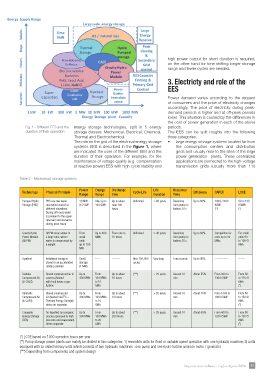
Fig. 1 - Different EES and the energy storage technologies, split in 5 energy periods.
duration of their operation storage classes: Mechanical, Electrical, Chemical, The EES can be split roughly into the following
Thermal and Electrochemical. three categories:
The role on the grid of the electrical energy storage • large energy storage systems located far from
systems EES is described in the fgure 1, where the consumption centers and distribution
are indicated the uses of the different EES and the grids and usually near to the sites of the large
duration of their operation. For example, for the power generation plants. These centralized
maintenance of voltage quality (e.g. compensation applications are connected to the high-voltage
of reactive power) EES with high cycle stability and transmission grids (usually more than 110
Table 2 - Mechanical storage systems
Power energy Discharge life response
technology Physical Principle cycle life effciency caPeX lcoe
range range time Duration time
Pumped Hydro PHS use two water 10 MW Also up to Up to about Unlimited > 80 years Reversing Up to 80% 1000–1500 60 to 130
Storage (PHS) reservoirs located at to 2 GW 100 GWh max 100 from pump to €/kW €/kWh
different elevations. hours turbine 30 s (**) (*)
During off hours water
is pumped to the upper
reservoir and viceversa
during peak hours
Gravity Hydro GHPM stores water in From Up to 400 From one to Unlimited > 40 years Reversing Up to 80% Competitive for For small
Power Module a large tube, where small MWh 10 hours from pump to units up to 50 units 60
(GHPM) water is compressed by units turbine 25 s MWe to 100 €/
a weight up to 100 kWh
MW
Flywheel Rotational energy is Small ---- -------- Also 100,000 Very long Few seconds Up to 95% -------------- ------
stored in an accelerated storage cycles
rotating cylinder (1 MW)
Diabatic Stored compressed air in Up to From Up to about (***) > 20 years Around 10 About 55% From 800 to From 50
Compressed Air caverns (heated 400 MWe 100 MWh 10 hours min 1300 €/kW to 120 €/
(D-CAES) with fuel) drives a gas to 10 kWh
turbine GWh (*)
Adiabatic Stored compressed Up to From Up to about (***) > 20 years Around 10 About 70% From 1000 to From 80
Compressed Air air (heated via TES – 400 MWe 100 MWh 10 hours min 1600 €/kW to 150 €/
(A-CAES) Thermal Energy Storage) to 10 kWh
drives an expander GWh (*)
Cryogenic Air liquefed by cryogenic Up to From Up to about (***) > 25 years Around 10 About 60% From 600 to From 80
Energy Storage process (pumped to high 300 MWe 100 MWh 200 hours min 1200 €/kW to 120 €/
(CES) pressure and evaporated) to 20 kWh
drives expander GWh (*)
(*) LCOE based on 1000 operation hours per year
(**) Pump storage power plants can mainly be divided in two categories: 1) reversible units for fxed or variable speed operation with one hydraulic machine; 2) units
equipped with so called ternary units which consists of two hydraulic machines : one pump and one hydro turbine and one motor / generator
(***) Depending from components and system design
Impiantistica Italiana - Luglio-Agosto 2014 43