
Page 81 - Industrial Plants
P. 81
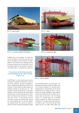
Pict. 20 - load out gates                          Pict. 21 - rotation


            Pict. 22 - connection of gate and fishing beam     Pict. 23 - a lowering the  gate


            installation area by the tugboats. The barge was
            moored  underneath  the  launching  system  previously
            laid onto the caissons. In order to reach for the correct
            positon for the connection of the mobile gate with the
            fishing beam (supported by the strand jacks on top of
            the launching system) it was necessary to execute a
            180 degrees rotation. This operation was executed by


              This operation will definitely represent
             another landmark in the history of naval
                          engineering

                                                      Pict. 24 - lowering the gate
            the SPMTs (pict. 21), which were also used to get the
            mobile barrier underneath the fishing beam. During all
            the  previous  operations,  the  barge  was  ballasted  in   was automatically freed from the “fishing beam”. The
            order to compensate the weights and movement of the   fishing beam was lifted and taken into position ready
            structures. The fishing beam was gently lowered and   for  the following installations. As mentioned  above,
            eventually connected to the gate (pict. 22) . After   Fagioli prepared a “transport beam structure for the
            connection, the gate was lifted by No. 4 strand jacks   repositioning of the launching system. In order to
            positioned on top of the lifting structure and the barge   execute the following installations, Fagioli used the
            was sailed away. The mobile gate was lowered into the   transport beam (positioned onto the barge) to lift the
            water by the strand jacks connected to the fishing   gantry system and reposition it onto the following
            beams  (pict.  23-24) .  The  final  operation  was  the   caissons. The transport beam was a retractable
            connection of the gate with the caisson after checking   structure positioned onto SPMTs and provided with
            the  correct  positioning  (pict.  25).  This  last  operation   strand jacks. The transport beams were skidded to
            was extremely precise and checked by waterproof   the outside to get in contact with the gantry lifting
            cameras. Once the connection was executed, the gate   system (pict 26). The gantry lifting system was


                                                                                    IndustrIal Plants - May 2017
                                                                                                                   79