
Page 91 - Impiantitica industriale
P. 91
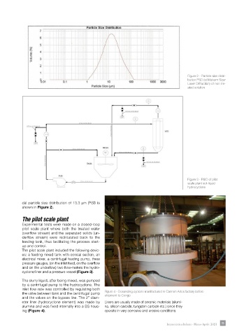
Figure 2 - Particle size distri-
                                                                                               bution PSD (at Malvern Sizer
                                                                                               Laser Diffraction) of non tre-
                                                                                               ated solution


                                                                                               Figure 3 - P&ID of pilot
                                                                                               scale plant soli-liquid
                                                                                               hydrocyclone


            dal particle size distribution of 13.3 µm (PSD is
            shown in Figure 2).

            The pilot scale plant

            Experimental tests were made on a closed-loop
            pilot scale  plant where both the treated water
            (overflow stream) and the separated solids (un-
            derflow  stream)  were  recirculated  back  to  the
            feeding tank, thus facilitating the process start-
            up and control.
            The pilot scale plant included the following devic-
            es: a feeding mixed tank with conical section, an
            electrical mixer, a centrifugal feeding pump, three
            pressure gauges, (on the inlet feed, on the overflow
            and on the underflow) two flow-meters the hydro-
            cyclone/liner and a pressure vessel (Figure 3).

            The slurry liquid, after being mixed, was pumped
            by a centrifugal pump to the hydrocyclone. The
            inlet flow rate was controlled by regulating both
            the valve between tank and the centrifugal pump   Figure 4 - Desanding cyclone manifactured in Cannon Artes factory before
            and the valves on the bypass line. The 2” diam-  shipment to Congo
            eter liner (hydrocyclone element) was made by   Liners are usually made of ceramic materials (allumi-
            alumina and was fixed internally into a SS hous-  na, silicon carbide, tungsten carbide etc.) since they
            ing (Figure 4).                           operate in very corrosive and erosive conditions.


                                                                                     Impiantistica Italiana - Marzo-Aprile 2021  85