
Page 101 - 83
P. 101
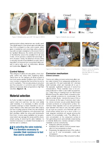
Figure 1. Butterfly valves up to 96” 150 class for SWCC           Figure 2. Butterfly valve concept


            sealing system where elastomers are mostly used.
            The overall weight of the valve is approximately less
            than 50% compared to other valve models, which
            gives a substantial cost advantage when using al-
            loys with corrosion resistance to the environment to
            be handled. Moreover, the end-to-end dimension
            of the Butterfly valve is the smallest from all valve
            model, which provide a substantial advantage in
            term of space. Finally, the absence of body cavity
            is reducing the risk of accelerated corrosion due to
            deposition of dissolved and suspended solids pre-
            sent in saline water such as carbonates, silicates
            and hydroxides. (figure 1 - 2).
                                                      Figure 3. K-LO Butterfly Control         Figure 4. Dyna-Lok Butterfly
            Control Valves                                                                     Control valve 72’’ for
            This category of valves includes globe, check, but- Corrosion mechanism            Hyundai valve 94’’ for Maire
                                                                                               Tecnimont
            terfly, control ball, safety relief, regulating valves.   Crevice corrosion
            This is from far the category of valves subject to
            the most severe service condition due to their pri-  Crevice and pitting corrosion extensively affect car-
            mary function to regulate the flow in the line and to   bon steel material if not adequately protected but
            control cavitation. This includes pressure reduction   also austenitic 316 and martensitic 431 stainless
            and flow reduction or control in case of throttling   steel materials, which are materials still in use in
            service and expose valve components to high fluid   the  seawater  application  because  of economics
            velocities. (figure 3 - 4).               considerations.  These materials have to be pro-
                                                      perly protected to resist to see water environment,
                                                      e.g. rubber lining or coatings such as FBE (Fusion
            Material selection                        Bonded Epoxy) for carbon steel, or providing ade-
                                                      quate cathodic protection to components of the
                                                      valve in contact (body – stem) in the case of 316 or
            As fluids handled in desalination are corrosive to   431 materials. In the case of stainless steel mate-
            carbon steel and cast iron, two low cost widely   rial, crevice corrosion occurs under deposit of any
            used materials, it is necessary to either provide   corrosion products on component’s surface. So-
            protective coatings to these materials or use cor-  metimes these deposits work as semi-preventive
            rosion resistant ones. Because valves often disturb   layer between the medium and the metal surface
            the flow in piping systems where they are installed,   but as soon as corrosion ions find their path to a
            they can generate turbulence, with associated high   small surface defect such as a micro crack or a
            fluid velocities, within the valves and downstream   hole, stagnant conditions will subsist allowing the
            from them. In some cases cavitation can be gene-  creation of concentration cells. The difference in
            rated which can damage the valves and the down-  ions concentration at the component surface is
            stream piping. In selecting the valve material, it is   then generating anodic and cathodic areas leading
            therefore necessary to consider their resistance to   to material destruction. Crevice corrosion on these
            fast flow and to cavitation.              materials could be controlled by:
                                                      •   Adequate cathodic protection
                 In selecting the valve material,     •   Increased flow velocity that will prevent depo-
                 it is therefore necessary to         •   sition on the component surface
                                                         Decreasing the aggressiveness of the medium
            “consider their resistance to fast           such as Cl  ions concentration, acidity and
                                                                  -
                 flow and to cavitation                  temperature
                                                      •   Periodical cleanliness of the component surface


                                                                                 Impiantistica Italiana - Settembre-Ottobre 2020  97 97