Page 49 - Impiantistica industriale
P. 49

Purified syngas

                                                                            Component      u.m.        Value
                                                                            H              %mol         39.1
                                                                             2
                                                                            CO             %mol         42.6
                                     Component      U.m.          Value     CO 2           %mol         12.8
            Syngas exiting from the acidic   Wet basis                      H O            %mol         0.4
            columns of each gasifi cation line                              N 2            %mol         4.8
            is collected and sent to a com-  C      % weight      41.7       2
            mon section based on alkaline   H       % weight       6.0      CH4            %mol         0.21
            scrubbing column, wet elec-  O          % weight      19.0      Arg            %mol
            trostatic precipitators (WESP)   N      % weight      0.70      H S            ppm          0.01
                                                                             2
            and subcooling column. Water                                    COS            ppm          0.1
            stream collected from the bot-  S       % weight       0.2
            tom of the washing columns   Cl         % weight       1.1      HCN            ppm          0.1
            due to the potential content   Moisture  % weight     13.5      HCl            ppm          0.1
            of  pollutants are  routed  to  the   Inert  % weight  17.8     Hg             ppm           -
            WasteWater Treatment unit.
            Gasifi er works  under  quite  at-  LHV  MJ/kg        17.9      PM             ppm           -
            mospheric pressure achieving   Table 2 - Waste used for the case study   Table 3 - Syngas composition.
            at the end of cleaning section   (Mixture 50% RDF-50% Plastics).
            pressure in order of few mbar. It
            derives that a compression section is needed before rout-  ing from selected end product, a conditioning step aiming at
            ing the syngas to downstream section. In order to assure   adjustment of H  and CO content is required [7-9].
                                                                  2
            stable condition in terms of syngas pressure and fl owrate   Once applied for hydrogen production, the conditioning
            at suction of compressors, a gas holder is installed be-  section will consist of a shift section and hydrogen purifi ca-
            tween the gasifi cation section and compression.   tion through pressure swing adsorption.
            The cleaned syngas still contains sulphur compounds
            mainly in the form of H S and COS together with residual
            chlorine, HCN and trace of Hg. Once compressed, syngas  2. Waste to Hydrogen production
                            2
            is routed to the purifi cation section involving the following   The proposed waste to hydrogen case study will be de-
            step: removal of residual dust and metals, removal of HCl,   veloped  around  a  waste  feedstock  having  an  average
            hydrolysis of the COS and HCN, H S removal through an   composition describing a mixture of 50% RDF and 50%
                                     2
            oxy-reduction system and a fi nal polishing step based on   plastic residues. Resulting mixture composition is reported
            zinc oxide absorbents in order to reduce sulphur content   in Table 2.
            down to ppb as required by catalyst adopted for down-  By applying the process scheme depicted in fi gure 2, re-
            stream synthesis.                          sulting syngas composition at the end of purifi cation sec-
            The high temperature regime and the use of a waste as   tion have a composition reported in Table 3.
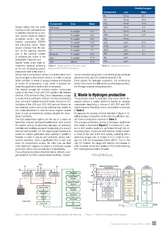
            feedstock, requires dedicated maintenance work around   The process architecture aiming at hydrogen production
            the  gasifi er  aiming  at  preventing  damages  on  refractory   from waste is depicted in Figure 3. To increase di H  con-
                                                                                           2
            materials and avoiding excessive fouling along the quench   tent a shift reaction section is performed through two in-
            wall and sedimentation. On this regard a plant architecture   tercooling steps. To promote shift reaction, medium steam
            based on multiple gasifi cation lines working in parallel is   is mixed at the inlet of the shift reactor, operating with a
            foreseen in order to assure plant availability during main-  steam/dry-syngas ratio of at least of 1.5 in order to man-
            tenance operation: when a gasifi cation line is kept shut   age the shift exit temperature below 480°C. Due to the
            down for maintenance service, the other lines are kept   high CO content, two stage shift reaction are foreseen in
            under maximum capacity to assure a continuous syngas   order to proper control any variation of CO content deriving
            production with a minimum reduction of productivity.   from heterogeneous nature of waste.
            The purifi cation procedure described above, delivers a syn-
            gas suitable to be fed to catalyst-based synthesis. Depend-  (1)  CO+H O ßà CO +H
                                                                         2      2  2


                                                                    ASU
                                                                         GASIFICATION AND PRELIMINARY   SYNGAS   SYNGAS
                                                                             GAS CLEANING   PURIFICATION  CONDITIONING
                                                                     O 2 + N 2
                                                                      NG
                                                                                             et
                                                                                             a
                                                                                                l
                                                                                               h
                                                                                              s
                                                                                              /
                                                                                              l
                                                                                               C
                                                                                                o
                                                                                                ri
                                                                   WASTE                    M Metals/Chlorine n e
                                                                                             removal
                                                                      HT – Gasification  HT – Gasification  HT – Gasification  Shift reaction
                                                                                                           steps
                                                                       & cleaning  & cleaning  & cleaning  Hydrolysis
                                                                 Inert granulate             COS (HCN)
                                                                                                           PSA      H2
                                                                                             Hg removal
                                                                   Sludge to   Alkaline scrubber,   H 2 S
                                                                    WWT     subcooling and  WESP  Removal  Purge
                                                                             Syngas storage               gas
                                                                                              H 2 S
                                                                                             deep polishing
                                                                                                     MP Steam
                                                                            Syngas compression
                                                                                          Condensate
                                                                                                                Flue gas
                                                                                       Demi water      Auxiliary boiler
                                                                                          Fuel
            Figure 2 - Block scheme: Gasifi cation and syngas primary gas cleaning   Figure 3 - Waste to Hydrogen block diagram
                                                                                  Impiantistica Italiana - Gennaio-Febbraio 2022  45 45
   44   45   46   47   48   49   50   51   52   53   54