
Page 86 - 101
P. 86
SUPPLY AND SERVICES
Where: D = impeller diameter , K, K = coef- ded on the blade, while on wheels provided with
1
ficients > 1 wear plates the discontinuity of the fillet weld may
The coefficients K and K depend on the diameter be badly eroded. In such a case the butt weld is
1
increase and the tip angle. mandatory (fig. 3 B) and the tip must be reinfor-
The effect on the fan performance curves is qualita- ced with the half-discs welded to the side cone and
tive the same shown in fig. 1. back plate. In the airfoil blades, where usually no
dust load is present, the tips may be fillet welded or
screwed as shown in the fig. 3 C.
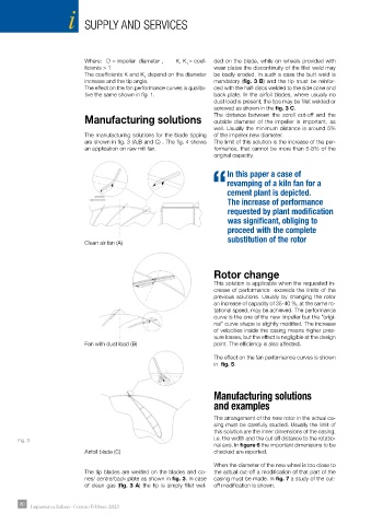
Manufacturing solutions The distance between the scroll cut-off and the
outside diameter of the impeller is important, as
well. Usually the minimum distance is around 5%
The manufacturing solutions for the blade tipping of the impeller new diameter.
are shown in fig. 3 (A,B and C) . The fig. 4 shows The limit of this solution is the increase of the per-
an application on raw mill fan. formance, that cannot be more than 5-8% of the
original capacity.
In this paper a case of
revamping of a kiln fan for a
“cement plant is depicted.
The increase of performance
requested by plant modification
was significant, obliging to
proceed with the complete
substitution of the rotor
Clean air fan (A)
Rotor change
This solution is applicable when the requested in-
crease of performance exceeds the limits of the
previous solutions. Usually by changing the rotor
an increase of capacity of 35-40 %, at the same ro-
tational speed, may be achieved. The performance
curve is the one of the new impeller but the “origi-
nal” curve shape is slightly modified. The increase
of velocities inside the casing means higher pres-
sure losses, but the effect is negligible at the design
Fan with dust load (B) point. The efficiency is also affected.
The effect on the fan performance curves is shown
in fig. 5.
Manufacturing solutions
and examples
The arrangement of the new rotor in the actual ca-
sing must be carefully studied. Usually the limit of
this solution are the inner dimensions of the casing,
Fig. 3 i.e. the width and the cut off distance to the rotatio-
nal axis. In figure 6 the important dimensions to be
Airfoil blade (C) checked are reported.
When the diameter of the new wheel is too close to
The tip blades are welded on the blades and co- the actual cut-off a modification of that part of the
nes/ centre/back plate as shown in fig. 3. In case casing must be made. In fig. 7 a study of the cut-
of clean gas (fig. 3 A) the tip is simply fillet wel- off modification is shown.
80 Impiantistica Italiana - Gennaio-Febbraio 2023