
Page 85 - 101
P. 85
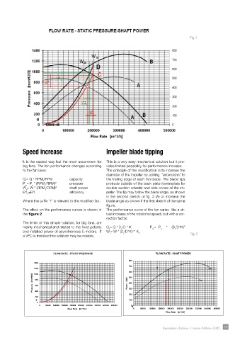
Fig. 1


            Speed increase                            Impeller blade tipping

            It is the easiest way but the most uncommon for   This is a very easy mechanical solution but it pro-
            big fans. The fan performance changes according   vides limited possibility for performance increase.
            to the fan laws:                          The principle of the modifi cation is to increase the
                                                      diameter of the impeller by adding  “extensions” to
            Q = Q * RPM /RPM        capacity          the trailing edge of each fan blade. The blade tips
                      r
              r
            P = P  * (RPM /RPM) 2   pressure          protrude outside of the back plate (centreplate for
                       r
             sr

                 s
            W = W * (RPM /RPM) 3    shaft power       double suction wheels) and side cones of the im-
              r
                       r
            Eff. =Eff.              effi ciency       peller. The tip may follow the blade angle, as shown
               r
                                                      in the second sketch of fi g. 3 (A) or increase the
            Where the suffi x “r” is relevant to the modifi ed fan.   blade angle as shown if the fi rst sketch of the same
                                                      fi gure.
            The effect on the performance curves is shown in   The performance curve of the fan varies  like a vir-
            the figure 2.                             tual increase of the rotational speed, but with a cor-

                                                      rection factor.
            The limits of this simple solution, for big fans, are
            mainly mechanical and related to the fi xed polarity   Q = Q * D /D * K       P = P  * (D /D*K)
                                                                                            2
                                                       r
                                                                                 s
                                                                                        r
                                                                             sr

                                                             r
            and installed power of asynchronous E-motors.  If   W = W * (D /D*K) * K
                                                                   3
                                                              r
                                                       r
                                                                      1
            a VFD is installed this solution may be reliable.                                  Fig. 2
                            FLOW RATE - STATIC PRESSURE                       FLOW RATE - SHAFT POWER
                                                                 800
                  1400
                                                                 700
                  1200                                                         0                        1480
                                                                 600
                  1000
                 Pressure   [mmH2O]  800                        Power   [kW]  400                   1300
                                                                 500
                  600
                                                                 300
                  400
                                                                 200
                  200
                   0 0 0                                         100
                   0
                     0  50000  100000 150000 200000 250000 300000 350000 400000 450000  0 0 0 0 0 0
                                   Flow Rate   [m^3/h]             0   50000  100000  150000  200000  250000  300000  350000  400000  450000
                                                                                   Flow Rate   [m^3/h]
                                                                                  Impiantistica Italiana - Gennaio-Febbraio 2023  79