
Page 61 - impiantistica_5_15
P. 61
pyrobreaker is water cooled and the water, besides
providing the cooling, contributes to the operation
of the switching section too.
Fig. 3 - Static Circuit Breaker and Control System Cubicle The discharge resistor and
the voltage clamp circuit
The Static Circuit Breaker
The SCB is based on IGCTs devices provided The discharge resistance value is determined within
a range defined by two main constraints: the maxi-
with suitable snubber circuits, thus allowing a soft mum voltage across the superconductive coils and
the maximum allowable I2t on quenched coil after
switching condition which assures the capability of quench detection.. The I2t depends on the delay
from the QPC command to the QPC intervention
interrupting a higher current value with respect to a and on the resistance value which determines the
discharge time constant.
snubber-less condition (figure 3). The final values of PFC and TFC QPC Discharge
Resistors (DR) are 0.19 and 0.0075 Ω respectively.
To improve reliability, the total number of IGCT bran- The resulting DR for TFC in particular, resulted from
a deep optimization process. QPC DRs are natural
ches in parallel was determined with the following air cooled but, since the TFC DRs are installed in
a semi-outdoor area, a quite high operating tem-
approach: first of all a redundant branch was pro- perature is acceptable. Assuming 350 ºC as the
maximum resistor temperature and exploiting the
vided; this means that the Static HCB is able to resistance variation with the temperature, it was
possible to reduce its value from 0.11 Ω to 0.075
interrupt the maximum current with one branch Ω ,thus allowing to limit the applied voltage to the
TFC below 2 kV and the magnet I2t below 4 GA2s.
less, without requiring intervention of the backup Moreover, the minimization of the stray inductance
of the resistor and of the connections to the switch-
protection. Then, the es, and the design of suitable clamp capacitors to
be connected in parallel to the resistor allow also
To improve reliability, the total number number of the n-1 de- limiting the peak transient voltage within the maxi-
of IGCT branches in parallel was vices in parallel was mum specified value of 2.8 kV.
defined assuming that
determined with the following approach: they have to sustain
first of all a redundant branch was the worst operating
provided; this means that the Static condition remaining
well below the maxi-
HCB is able to interrupt the maximum mum junction tempe-
current with one branch less, without rature suggested by
requiring intervention of the backup the manufacturer.
The basic module is
protection capable to host bidi-
rectional IGCT bran-
ches including the related snubber circuits, current
sharing resistors, series diode and free-wheeling
diode in parallel to each IGCT to guarantee that no
reverse voltage is applied to the IGCT. Nidec ASI
proposed the same design of the SCB for TFC and
PFC QPCs; however, since the current in the TFC
QPCs is unidirectional, it was avoided to mount the
IGCTs in anti-parallel. The size and the layout of the
basic power module were defined with the aim to
facilitate its handling and maintenance.
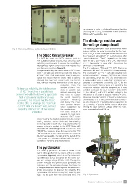
The pyrobreaker Fig. 4 - Pyrobreaker
The back-up protection in case of failure of the
hybrid CB is performed by means of the so-called
pyrobreaker (figure 4), which is an Explosive Acti-
vated Breaker (EAB), designed for the same cur-
rent and voltage ratings (26 kA, 5 kV). The ignition
system includes the ignition pulse generator, the
detonator and the explosive charges; the triggering
of the pyrobreaker is tested against the electroma-
gnetic disturbance to improve the reliability. The
pyrobreaker intervention is very fast, requiring less
than 1ms to open from the command time. The
Impiantistica Italiana - Settembre-Ottobre 2015 59