Page 70 - Impiantistica Italiana 5/2016
P. 70

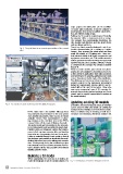
Fig. 2 - The point cloud is an accurate representation of the scanned                      major projects the whole plant can be modelled.
plant                                                                                      For minor plant extensions, it may be sufficient to
                                                                                           model just the tie-in items to facilitate clash detec-
                                                                                           tion and efficient piping design.
                                                                                           Building the 3D model is straightforward. Basically,
                                                                                           the operator clicks a component such as a pipe.
                                                                                           The software then automatically determines the
                                                                                           size, location and direction, and also inserts items
                                                                                           such as elbows and tees.
                                                                                           One of our clients recently developed a set of up-
                                                                                           to-date documentation for a refinery in Eastern
                                                                                           Europe. They scanned the whole plant and then
                                                                                           made 3D models of 173 piping runs. These mo-
                                                                                           dels included details of all piping components and
                                                                                           equipment connections, etc. The models were also
                                                                                           used to produce isometric drawings and to provide
                                                                                           input for the pipe stress analysis software. Overall,
                                                                                           a comprehensive package was produced quickly
                                                                                           (figure 4).
                                                                                           These accurate models, point clouds and photo-
                                                                                           graphs are now available to all authorized users for
                                                                                           a wide variety of applications from daily operations
                                                                                           and maintenance to planning, giving improved data
                                                                                           access throughout the life cycle of the installation.
                                                                                           The efficiency and accuracy of laser scanning is in
                                                                                           marked contrast to the frustrations encountered
                                                                                           during the manual plant surveys, which I was in-
                                                                                           volved with at the start of my career. I have also
                                                                                           seen some unexpected uses of 3D scanning, for
                                                                                           example documenting historic buildings and crime
                                                                                           scenes and to support special effects creation in
                                                                                           the movie industry.

Fig. 3 - An example of a point cloud integrated with digital photographs.                  Updating existing 3D models

                                    FPSO, which had to be modified. Although there         Sometimes the point cloud and Smart 3D software
                                    was extensive documentation for the unit, spread       can be used to verify and update an existing 3D
                                    over 360,000 documents, there was no 3D model          model, instead of building a 3D model from scratch.
                                    available. Hence, they commissioned a survey-          This is an efficient way of obtaining as-built docu-
                                    ing company to do a full laser scan of the FPSO,       mentation and identifying differences between the
                                    moored 50 km off the coast of Western Australia.
                                    The point clouds were then linked to the schemat-
                                    ics, text documents and spreadsheets using Smart-
                                    PlantĀ® Fusion, an Intergraph solution that enables
                                    users to find, capture, organize, link, and visualize
                                    large volumes of engineering data and documents.
                                    Fusion is available through a web portal so that all
                                    the designers and contractors involved in the modi-
                                    fication project had access to uniform and accurate
                                    data. Consequently, during the modification project
                                    the schedule and costs could be reduced and mis-
                                    takes avoided. All this was possible even without
                                    building a full 3D model.

Building a 3D model                                                                        Fig. 4 - Developing a 3D model in Intergraph Smart 3D

Where appropriate, the next step is to build a 3D
model in Intergraph Smart 3D design solution. For

68 Impiantistica Italiana - Settembre-Ottobre 2016
   65   66   67   68   69   70   71   72   73   74   75