
Page 39 - Impiantistica Italiana
P. 39
double circuit one on the left side of figure 4, with transformation does not pose limits to the power
one 3 phase AC circuit in a vertical disposition on increase by adopting a DC OHTL with poles in a
both sides of the tower vertical position and suitable conductors.
According to the length / type of the AC insulator There are no limits to imagination for possible so-
strings and according to available clearances to the lutions to improve the power transfer capacity of
tower and to the ground, the easiest transforma- existing transmission lines or transmission line cor-
tion should be (figure 4 in the middle) the one im- ridors. Different possible solutions with different
plying the simple substitution of AC insulators with power increase / costs can be considered, and the
the maximum possible length of the DC ones (and key issues are the following:
therefore the maximum DC voltage), ), and con- • the actual possibility to take out of service the
necting in parallel at the line terminals the 3 phases specific AC line and for how long during the
on the left to form one pole of the new DC line and “transformation period”;
the 3 phases on the right connected in parallel as • specific problems relevant to existing anchor
the other DC pole; but this does not allow substan- towers, angle towers etc.;
Fig. 5 - Substitution in the tial power improvements. • the length of the line involved, even if entering /
same RoW of a 245 kV The maximum upgrading is given by eliminating the exiting from substations could consider a new
Italian double circuit line arms of existing AC towers and substituting them transformed line as a series of 2-3 original AC
equipped with single diam- with two new arms in a suitable position to match ones;
eter 31 mm ACSR conduc- mechanical and electrical stresses. From various • the cost / space of DC stations in case of tran-
tor per phase studies performed in many countries the power up- sformation of AC into DC lines;
grading could be in the range of 3-5 times • the actual “power increase” acceptable by the
the original one. The possible elimination networks at both ends of the line;
of all the steel arms and the adoption of • the local standards (including possible hot line
horizontal V hinged insulator assemblies maintenance, RIV, AN, EMF limits etc.) and
has also revealed to be interesting. conditions posed by technical problems (e.g.
Figure 4 shows the results of studies on local contamination) by accesses and logistics
the same original 245 kV Italian double and by local costs including the cost of losses.
circuit line of paragraph 2.1.2. The AC
transfer capacity of 350 MW is increased The key issue is the development of technologies
to 550 MW with the simplest transforma- and equipment and the organization of works in
tion. The power increase to 1560 MW is order to minimize the unavailability of the power
obtained with the modification of tower transmission during the revamp.
arms. The reported values refer to opera-
tion at the same current density of 1 A/
2
mm . 2.2 New types of towers for
AC lines
2.1.4 Substitution of an For AC lines, the main efforts have been placed sin-
existing AC line with a ce many years in developing:
compact one at a higher • new towers allowing increased transfer capa-
city (TC) for long transmission, with the mini-
voltage or with a DC one in mum RoW width;
the same RoW • eco towers / compact lines with a “more ac-
ceptable“ impact on the environment.
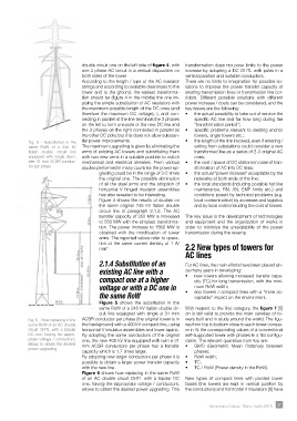
Figure 5 shows the substitution in the
same RoW of a 245 kV Italian double cir- With respect to the first category, the figure 7 [5]
cuit line equipped with single ø 31 mm on is still valid to provide the main varieties of to-
Fig. 6 - How replacing in the ACSR conductor per phase (the original tower is in wers built and in study around the world. The figu-
same RoW of an AC double the background) with a 400 kV compact line, using res from top to bottom close to each tower compa-
circuit OHTL with a bipolar horizontal V insulator assemblies and lower spans. re in % the corresponding values of a conventional
DC one, having the appro- By adopting the same conductors of the original self-supported tower with phases in a flat configu-
priate voltage / conductors, one, the new 400 kV line equipped with twin ø 31 ration. The relevant quantities from top are:
allows to obtain the desired mm ACSR conductors per phase has a transfer • GMD (Geometric Mean Distance) between
power upgrading
capacity which is 1.7 times larger. phases;
By adopting new larger conductors per phase it is • RoW width;
possible to obtain a larger power transfer capacity • TC;
with the new line. • TC / RoW (Power density in the RoW).
Figure 6 shows how replacing in the same RoW
of an AC double circuit OHTL with a bipolar DC New types of compact lines with pivoted tower
one, having the appropriate voltage / conductors, bases (the towers are kept in vertical position by
allows to obtain the desired power upgrading. This the conductors) and horizontal V insulators [6] have
Impiantistica Italiana - Marzo-Aprile 2018 37