
Page 63 - Impiantistica industriale
P. 63
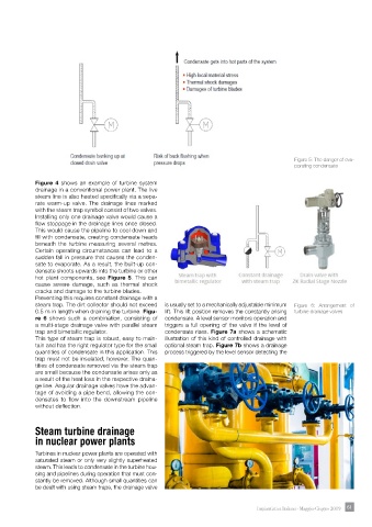
Figure 5: The danger of eva-
                                                                                               porating condensate


            Figure 4 shows an example of turbine system
            drainage in a conventional power plant. The live
            steam line is also heated specifically via a sepa-
            rate warm-up valve. The drainage lines marked
            with the steam trap symbol consist of two valves.
            Installing only one drainage valve would cause a
            flow stoppage in the drainage lines once closed.
            This would cause the pipeline to cool down and
            fill with condensate, creating condensate heads
            beneath the turbine measuring several metres.
            Certain operating circumstances can lead to a
            sudden fall in pressure that causes the conden-
            sate to evaporate. As a result, the built-up con-
            densate shoots upwards into the turbine or other
            hot plant components, see  Figure 5. This can
            cause severe damage, such as thermal shock
            cracks and damage to the turbine blades.
            Preventing this requires constant drainage with a
            steam trap. The dirt collector should not exceed   is usually set to a mechanically adjustable minimum   Figure 6: Arrangement of
            0.5 m in length when draining the turbine. Figu-  lift. This lift position removes the constantly arising   turbine drainage valves
            re 6  shows such a combination, consisting of   condensate. A level sensor monitors operation and
            a multi-stage drainage valve with parallel steam   triggers  a full  opening of  the valve  if the level  of
            trap and bimetallic regulator.            condensate rises. Figure 7a shows a schematic
            This type of steam trap is robust, easy to main-  illustration of this kind of controlled drainage with
            tain and has the right regulator type for the small   optional steam trap. Figure 7b shows a drainage
            quantities of condensate in this application. This   process triggered by the level sensor detecting the
            trap must not be insulated, however. The quan-
            tities of condensate removed via the steam trap
            are small because the condensate arises only as
            a result of the heat loss in the respective draina-
            ge line. Angular drainage valves have the advan-
            tage of avoiding a pipe bend, allowing the con-
            densates to flow into the downstream pipeline
            without deflection.


            Steam turbine drainage
            in nuclear power plants

            Turbines in nuclear power plants are operated with
            saturated steam or only very slightly superheated
            steam. This leads to condensate in the turbine hou-
            sing and pipelines during operation that must con-
            stantly be removed. Although small quantities can
            be dealt with using steam traps, the drainage valve


                                                                                   Impiantistica Italiana - Maggio-Giugno 2019  61 61