
Page 64 - Impiantistica industriale
P. 64
componenTs
Figure 7a: Controlled drai-
nage with GESTRA NRG
211 sensor
Drainage valves are subject to special require-
ments in terms of wear resistance. Condensate
with temperatures of up to boiling point flows
through the valve at high pressure. The flash ste-
am created here accelerates the water particles
to enormous speeds, which can quickly lead to
blasting wear in the valves. A similar load occurs
when the valves are exposed to a high-speed
flow of steam/water mixture at the end of the
drainage phase.
Eroded seal seats can cause steam losses
across the entire operating time of the power
plant block and can only be repaired during the
next standstill. Figure 8 shows the typical da-
mage caused by blasting wear from evaporating
Figure 7b: Drainage pro- condensate. An adjustable time delay (TD) pre- water or two-phase flow.
cess
vents the valve from closing too quickly. If using a As well as the loss of valuable hot steam, the
steam trap, the lowest valve lift position is generally downstream condensate system is also expo-
between 10 – 25%. sed to unnecessary quantities of steam. If the
Highly wear-resistant condensate line leads to the condenser, the in-
troduction of hot steam can lead to performance
drainage valves losses at the cold end of the turbine. We there-
fore recommend regularly checking the drainage
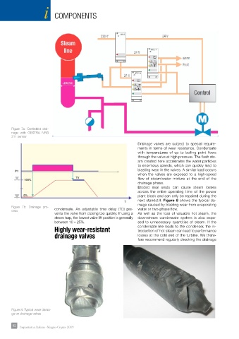
Figure 8: Typical wear dama-
ge on drainage valves
62 62 Impiantistica Italiana - Maggio-Giugno 2019