
Page 61 - Impiantistica industriale
P. 61
Basic requirements
Draining steam turbines and pipeline systems,
in particular live steam (LS) and the lines to and
from the reheater, is subject to the following re-
quirements.
• Safe removal of condensate
• Tight valve closing
• No loss of steam
• No banking-up of condensate in the turbine
drainage lines
• High wear resistance for long service lives
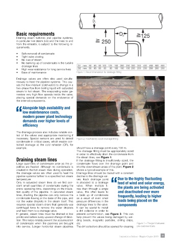
• Ease of maintenance Figure 1: Recommendation for drainage fitting
Drainage valves are often also used simulta-
neously to heat the pipeline systems. This cau-
ses the flow medium (cold water) to change in a
two-phase flow from boiling liquid with saturated
steam to hot steam. The evaporating water ge-
nerates very high flow speeds inside the valve,
placing special demands on the endurance of
the internal components.
Alongside high availability and
low maintenance costs,
“modern power plant technology
demands ever higher levels of
efficiency
The drainage process also includes reliable con-
trol of the valves and appropriate monitoring if
necessary. Special sensors are used to detect Figure 2: Insufficiently sized drainage fitting
condensate in critical cases, which enable con-
trolled drainage at the cold reheater (CR), for
example. should have a drainage point every 100 m.
The drainage fitting must be appropriately sized
in order to effectively drain the condensate from
Draining steam lines the steam lines, see Figure 1.
If the drainage fitting is insufficiently sized, the
Large quantities of condensate arise as the pi- condensate flows over the drainage point and
pelines are heated. Although no condensate is into the downstream areas of the plant. Figure 2
created in the hot steam lines during operation, shows a typical example of this.
the drainage valves are often used to heat the Drainage lines should be routed with a constant
pipeline systems further to a specified hot steam decline to the drainage val-
temperature. ves. Each drainage point Due to the highly fluctuating
Only in saturated steam lines do we find con- is allocated to a drainage feed of wind and solar energy,
stant small quantities of condensate during the valve. When multiple li- “the plants are being activated
entire operating time, depending on the insula- nes drain through a single
tion quality of the pipeline. In saturated steam valve, this often leads to and deactivated ever more
lines, draining the pipeline can only remove the a bank up of condensate frequently, leading to higher
condensate flowing at the base of the pipe, and as a result of even small
not the water droplets in the steam itself. This pressure differences in the loads being placed on the
requires special steam driers that generally use drainage lines to the valve. components
centrifugal force to remove the water droplets It can be useful to install
and feed them to a drainage valve. a dirt collector in order to
In general, steam lines must be drained at low prevent contamination, see Figure 3. This can
points and before every upward change of direc- help prevent the valves being damaged by wel-
tion. This helps reliably prevent the accumulation ding beads, magnetic particles, drilling chips,
of condensate when the pipelines are brought etc. Figure 1 – The joint between
into service. Longer horizontal steam pipelines The dirt collectors should be opened for cleaning pre-cast members
Impiantistica Italiana - Maggio-Giugno 2019 59