
Page 65 - Impiantistica industriale
P. 65
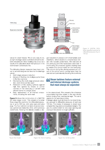
Figure 9: GESTRA ZK29,
                                                                                               three-stage flow restrictor for
                                                                                               differential pressures of up to
                                                                                               100 bar

            valves for steam losses. This is very easy to do,   ged reduction in pressure with intermediate swirl
            as tight drainage valves cool down almost to am-  chambers, which results in a simultaneous divi-
            bient temperature. Minor heating may occur as a   sion into multiple partial flows. The seal seat of
            result of the saturated steam temperature in the   the valve plug and the replaceable valve seat in
            downstream condensate line.               the housing are protected against blasting wear
                                                      by means of a control notch on the valve plug.
            The following design measures have been pro-  This occurs during the closing process as a re-
            ven to achieve long service lives for the drainage   sult of the control notch running faster than the
            valves:                                   seal seat and prematurely blocking the boreholes
            •   Multi-stage pressure reduction
            •   Division of the flow into multiple partial flows
                in the flow restrictor                    Steam turbines feature external
            •   Maintaining the multi-stage pressure reduc-
                tion, even when partially open            and internal drainage systems
            •   Protection of the sealing surfaces against “that must always be separated
                high  flow  speeds  by  means  of  control
                notches on the valve plug or tandem seat
                (double barrier in a single valve)
            •   Easy replacement of all internal compo-  in the sleeve insert. This prevents the otherwise
                nents, including the valve seat       unavoidable high flow speed in the seal shortly
                                                      before closing from causing damage. The same
            Figure 9 shows the construction of a GESTRA   applies to the opening process.
            ZK radial stage nozzle. This consists of a radial   Drainage valves, such as those for live steam lines,
            three-stage flow restrictor for differential pressu-  are exposed to differential pressures of well over
            res of up to 100 bar, with valve seat and valve   100 bar. This makes it necessary to install more
            plug. The flow restrictor consists of several slee-  complex flow regulators and seal seat designs. The
            ves pushed one inside the other, with numerous   use of a control notch for zero-wear opening and
            radial holes. Twisting the sleeves creates a sta-  closing of the valve is no longer sufficient.


            Figure 10a: Closed                                 Figure 10b: Start of opening               Figure 10c: Control position


                                                                                   Impiantistica Italiana - Maggio-Giugno 2019  63 63