
Page 97 - Impiantistica industriale
P. 97
spective air of influence of the floor.
No live load should be considered because S-BRP
is temporarily manned for maintenance only, there-
fore no personnel are permanently present during
the normal working time. However, for safety rea-
sons, the live load is applied. This load is applied
as uniform distributed pressure load on the building
floor, where no equipment is installed.
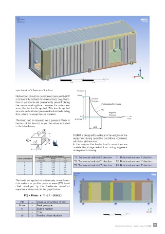
The blast load is assumed as a pressure Pmax in
function of the time td, as per the values indicated
in the table below,
S-BRM is designed to withstand the weights of the
equipment during operative conditions, combined
with blast phenomena.
In the analysis the twelve fixed connections are
modeled by a hinge restraint, according to general
arrangement drawing.
T1: Transversal restraint X direction R1: Rotational restraint X direction
T2: Transversal restraint Y direction R2: Rotational restraint Y direction
T3: Transversal restraint Z direction R3: Rotational restraint Z direction
The loads are applied simultaneously on each mo-
dule surface as per the pressure wave (PW) trend The load considered are:
chart developed by the Friedlander waveform Standard earth gravity;
equation and reported in the graph below. Live load;
Live Load (LL), the live load applied to the floor of
P(t) = Pmax ∙ e - t/td ∙ [ 1 - ( t/td ) ] the enclosure is equal to ;
The blast load for each face.
P(t) = Pressure in function of time
Pmax = Peak pressure The FEM final results are:
e = Euler’s number Stress Diagram – Time of max Detected Stress (Fi-
nite Element Methods)
t = Time
td = Positive phase duration
Impiantistica Italiana - Luglio-Agosto 2022 91