
Page 61 - Impiantistica Italiana
P. 61
by the low heat exchange coefficient resulting from Heaters “Design case” study
low flow velocity. The coke deposition on the inter- Results discussion – Flow regime
nal surface of the tubes increases the tube metal
temperature due to the coke resistance to heat To verify the flow regime of the process flow inside
transfer. the radiant coils, where vaporisation takes place,
On the other hand, liquid to vapour separation is two different models for horizontal tube lay out
the effect of not proper fluid velocity that leads to were considered:
unacceptable flow regime with liquid and vapour • Braun & Co. model, (reference: Braun J. G.
phases separation inside the coils. This situation “Process data book – Two phase pressure-
creates an uneven tube metal temperature along drop in pipes”);
the tubes. • Baker model (reference: Baker O. “Simulta-
All of these findings provided a very reasonable ex- neous flow of oil and gas” Oil and gas Journal,
planation of alleged problems and were reflected in 53, 185-195).
site survey evidences (figure 3).
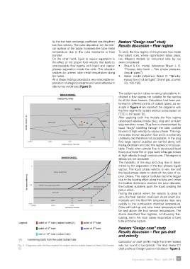
The radiant section tubes re-rating calculations in-
dicated a flow regime not suitable for the service
for all the three heaters. Calculation had been per-
formed in different points of radiant tubes, as ex-
ample in figure 4 are reported the diagrams with
the flow regime for radiant section tubes based on
FEED 3 for heater ∏2.
After applying both the models the flow regime
developed resulted inside plug, slug and annular/
slug transition zones. Slug flow is characterised by
liquid “slugs” travelling through the tube, pushed
forward at high velocity by vapour phase. This regi-
me is also known as piston flow and it is extremely
unsteady and therefore not acceptable. In the plug
flow large vapour bubbles are carried along with
the liquid stream and also this regime is not accep-
table. Finally when annular flow is developed liquid
flows as annular film on pipe walls while gas travels
at high velocity through central core. This regime is
steady but not advisable.
The instability of the slug and plug flow is deter-
mined by the separation of the two phases liquid/
vapour. The liquid phase velocity is very low and
the liquid phase starts to obstruct the pass of va-
pour phase. The vapour bubbles become bigger
due to the heating effect along the tube and, when
the bubble dimension reaches the tube diameter,
the bubbles suddenly push the liquid creating the
piston effect.
During the period where the velocity is close to
zero, the heat transfer coefficient drops down dra-
matically and the fluid film temperature rises very
quickly to the combustion chamber temperature.
Coke will build up and tube metal temperature will
be well above the limit service temperature. The
above described flow regimes, continuously fluc-
tuating, are in the most cases responsible of bent
tube and tube rupture.
Heaters “Design case” study
Results discussion – Flue gas draft
and velocity
Calculation of draft profile inside the three heaters
Fig. 4 – Diagrams with the flow regime for radiant section tubes based on feed 3 for heater was not found to be optimal. The fired heater ∏1
∏2 draft profile at Design case is indicated in figure 5.
Impiantistica Italiana - Marzo - Aprile 2018 59