
Page 62 - Impiantistica Italiana
P. 62
very high. For such a reason, the metal tempera-
ture could rise with serious risk of tubes damage.
Heaters “Max Allowable Load Case” -
Results
Following the heaters design case analysis, the th-
ree fired heaters were re-rated in order to calculate
the outlet temperature corresponding to the actual
outlet operating pressure and design outlet vapori-
sation percentage. The results of the analysis sho-
wed that considering current operating pressure
and required outlet vaporisation percentage, outlet
temperature specified on the original data sheets
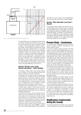
Fig. 5 - The fired heater ∏1 draft profile at Design case cannot be matched for all the heaters.
The draft profile was not acceptable. Pressure drop across the convection section was very
The draft profile was not acceptable. Pressure drop
low, due to very low flue gas velocity. Such low velocity creates an effect of flue gas buoyancy
across the convection section was very low, due to Process Study - Conclusions
inside the convection section, heavily affecting convective exchange. Being the flue gas
Two aspects were recognised as the main bottle-
very low flue gas velocity. Such low velocity creates
pressure higher at convection section outlet than at convection section inlet (draft available is
an effect of flue gas buoyancy inside the convec-
necks of heaters ∏1/∏2/∏3: fluid-dynamics and
higher than pressure drops through convection section), the flue gases discharge from radiant
thermo-dynamic issues.
tion section, heavily affecting convective exchange.
Being the flue gas pressure higher at convection
Even if with a different impact for each of the three
to convection section was penalised. Un-proper flue gas distribution on exchange surface,
section outlet than at convection section inlet (draft
heaters, the study clearly highlighted the very low
flue gas recirculation and channelling were likely happening. For this reason, hotter and
velocity of process fluid inside the coils. The reason
available is higher than pressure drops through
colder zones were probably created inside convection section with inefficient heat exchange.
convection section), the flue gases discharge from
was identified as the very low pressure drop throu-
Similar considerations were applicable also for П2 and П3. gh coils considered as design value, leading to very
radiant to convection section was penalised. Un-
proper flue gas distribution on exchange surface, large diameter heater tubes. The direct effect was
Heaters “Design Case” Study flue gas recirculation and channelling were likely the radiant section tubes overheating with perma-
happening. For this reason, hotter and colder zo-
Results Discussion – Other findings nent bending and tube rupture due to hot spots. As
far as heater ∏1 is concerned, the effect was even
nes were probably created inside convection sec-
tion with inefficient heat exchange. Similar conside- worse due to the symmetrical piping arrangement
rations were applicable also for ∏2 and ∏3.tion to the major issues
The heaters “Design Case” study brings evidence that, in addi control of process flowrate, not acceptable consi-
previously described, other items were not optimised. dering the very low fired heater pressure drop.
Heaters “Design case” study The flue gas velocity through the convection sec-
Results discussion – Other findings
tions of all the three heaters was extremely low. As
In particular, the convection section of fired heaters П2 and П3 was not verified to provide the
a consequence the heat transfer coefficient flue
required heater efficiency. Furthermore heater П2 convection section tubes are bare, with no
gas side was very poor and responsible of low heat
The heaters “Design case” study brings evidence
extended surface installed, there is no process reason for using such a configuration and the
recovery. Moreover, low velocity caused low flue
that, in addition to the major issues previously de-
scribed, other items were not optimised.
installation of extended surface would increase the heat recovery. gas side pressure drop promoting channelling and
In particular, the convection section of fired heaters flue gas buoyancy.
The heat recovered in convection section was not
∏2 and ∏3 was not verified to provide the required
Calculated tube metal temperature in coke fouling condition was in heater П1 very close to
heater efficiency. Furthermore heater ∏2 convec-
in line with specified heat balance being un-suffi-
the maximum operating temperature and for heater П3 was higher than the calculated
tion section tubes are bare, with no extended sur-
cient the installed surface. To balance heat not re-
face installed, there is no process reason for using
maximum allowable operating temperature. covered in convection section, additional heat had
such a configuration and the installation of exten- to be exchanged in radiant section.
ded surface would increase the heat recovery.
The air pre-heating system heat balance was not
The process flow-rate to the four passes of the П2 heater coils was controlled only through
Calculated tube metal temperature in coke fouling
verified and the heat demand to cope with convec-
symmetrical piping and not through control valve on each pass. Such a poor control method,
condition was in heater ∏1 very close to the ma-
tion sections requirements should be covered by
combined with the very low process pressure drop, led to uneven distribution of process flow-
ximum operating temperature and for heater ∏3
flue gas and combustion air exchanger. For such
was higher than the calculated maximum allowable
rate between the four passes: i.e. different flow-rate to each pass. a reason the calculated air temperature to each
operating temperature. burner was much higher than the specified value.
The missing duty have to be covered, once again,
The process flow-rate to the four passes of the ∏2
During the start-up period, when the flow-rate is lower than design value, the probability to
by radiant coils that as consequence will receive a
heater coils was controlled only through symme-
operate with one or more radiant section in dry condition is very high. For such a reason, the
trical piping and not through control valve on each
higher heat flux.
metal temperature could rise with serious risk of tubes damage.
pass. Such a poor control method, combined with
distribution of process flow-rate between the four Modifications implemented
the very low process pressure drop, led to uneven
passes: i.e. different flow-rate to each pass. during the revamp
During the start-up period, when the flow-rate is
Heaters “Max Allowable Load Case” The dewaxing heaters ∏1/∏2/∏3 were revamped
lower than design value, the probability to operate
Results with one or more radiant section in dry condition is in fully accordance with the recommendations of
60 Impiantistica Italiana - Marzo - Aprile 2018