
Page 69 - Impiantistica Italiana
P. 69
to the vacuum deaerator
column in order to reduce
oxygen concentration thus
avoiding corrosion problems
and bacterial proliferation.
Upstream the vacuum tower,
different chemical products
such as antifoaming and two
different types of biocides
were introduced for a further
inactivation of sulphate
reducing bacteria (SRB).
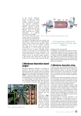
The vacuum tower was a two Figure 2. Scheme of membrane deaeration operation mode
stages columns composed by
two packed beds separated by
an hydraulic interstage seal; each packed bed
was filled by random nominal 2” polypropylene Artes Ingegneria is qualified by 3M
mass transfer packing type elements. Vapor as a system integrator for injection water
extraction from the two packed sections degassing
was made by the vacuum system which was
composed by 2 x 100 % liquid ring vacuum
pumps and one air ejector. Residual oxygen cartridge and the housing wall.
content in outlet water from the deaerator was As explained, the separation principle by membra-
50 ppb after packed sections. Because of the ne deaeration differs from other membrane sepa-
limited performance in oxygen removal of the rations such as filtration and gas separation. In fact
vacuum tower, the residual oxygen reduction in LiquiCel membrane deaeration selected for this
to the request value (lower than 20 ppb) was study, there is no convective flow through the pores
obtained only through oxygen scavenger dosing. since the membranes act as an inert support that
brings the liquid and gas phases into direct contact
without any dispersion.
3.Membrane deaeration based
project 3.1Membrane deaeration sizing
In order to carry out a comparison between mem-
Membrane deaeration represents a promising al- brane deaeration (MDA) and vacuum towers (VT)
ternative to the vacuum towers in the removal of based deaeration system, an executed VT based
dissolved oxygen from injection water, by providing project was analyzed. This project was compared
high efficiency mass transfer between gas and liquid. with the equivalent process obtained by replace-
Figure 1. They are based on the utilization of hydro- ment of vacuum towers with membrane deaeration
phobic microporous hollow fiber membranes made modules.
of polypropylene which contain large surface area. The sizing of the membrane deaeration system and
In a typical design, the water flows in one of the all the ancillaries, was made at the same inlet wa-
two membrane sides (shell side) while gas flows ter characteristics (flowrate, temperature and inlet
in the opposite lumenside: since the membrane oxygen concentration) and output process specifi-
is hydrophobic and cations of the vacuum towers based project.
contains very small In particular, membrane deaeration system sizing
pores, it does not was made by means of simulation Tool jointly with
allow the passage LiquidCell, by 3M, worldwide leader in membrane
of the water acting deaeration production. Once selected the number
as a stable barrier of modules, the vacuum level and the purity of the
between gas and Nitrogen used as stripping gas, a prediction of per-
liquid. formance based on the regression of experimental
As shown in Figu- data was provided by the tools.
re 2, water is fed in As pretreatment for seawater upstream to the
the MDA through a membrane deaeration, a combination of Dual me-
central distribution dia filters (> 98 % @ 2 µm) was selected. In fact, a
tube and is forced minimum filtration pretreatment was recommended
to follow a tortuous by LiquiCel in order to prevent potential membrane
path until reaching fouling and blockage: solid particles could create a
an anular space high pressure drop across the contactors and re-
Figure 1. Membrane Deaeration skid between the fiber duce the flow through the contactors system.
Impiantistica Italiana - Luglio-Agosto 2017 67