
Page 76 - Impiantistica industriale
P. 76
OPPORTUNITIES
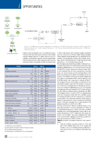
Figure 4 - Simplifi ed block scheme integrating unit operations of E-RWGS, electrolytic hydrogen production with Solid
Oxide Electrolysis Cell – SOEC, Alkaline Electrolyzer – AE, Polymer Electrolyte Membrane Electrolyzer – PEME amd
methanol synthesis.
catalyst and iii) avoiding the use of a reforming furnaces. to other metal species with increased catalytic properties
However, other electrifi ed reactor solutions could include such as it would occur in Nickel-Cobalt catalyst particles.
33
induction-heated reactors in which reactions occur on These solutions under development for electrifi ed SR ap-
catalysts constituted by magnetic particles having a high plication, can be exploited, possibly with a greater advan-
Curie temperature that inside a magnetic fi eld could be tage, also for E-RWGS reactors in which the reaction heat
selectively heated and possibly transfer the reaction heat would be ca. 1/5 of the heat required by SR.
We have hence examined the possibility of utilising the as-
TABLE 6 Case A Case B sociated CO2 emissions of a biomethane production plant
developing H&M balances for a process solution fed with
Purge 0% 10% 300 Nm3/h of carbon dioxide as a reference case. Brief-
Hydrogen consumption 875 895 Nm3/h ly it is mentioned that we have considered to compress
either, the carbon dioxide and the hydrogen fl ows at 50
[A] 2623,3 2683,3 KWth
MPa and subsequently to divide the hydrogen fl ow in two
Carbon dioxide consumption 300 300 Nm3/h streams. One stream is mixed with the carbon dioxide and
[B] 13,38 13,38 kmol/h the mixture is pre-heated at 650°C before entering in the
E-RWGS reactor that is assumed to operate at 950°C.
Methanol productionm (1) [J] 405,6 334,4 kg/h
The syngas at the exit of the reactor is cooled at 20°C for
9,73 8,03 TPD removing the water content from the reaction mixture and
[C] 12,66 10,44 kmol/h then mixed with a hydrogen fl ow for allowing the achieve-
ment of a methanol module M equal to 2 v/v. This adjusted
[D] 2243,2 1849,4 KWth
synthesis gas is then pre-heated to 250°C before entering
Carbon dioxide emission (2) [F] 13,56 116,73 kg/h into the methanol synthesis reactor operating at 50 MPa.
Gross power consumption [E] 468,5 384,6 kWel The obtained stream is cooled at 25°C for separating the
liquid and the gaseous phase and that is partially purged
Power production 105,7 181,6 kWel
for avoiding the build-up of inert molecules (e.g. methane)
Net power consumption [G] 362,8 203 kWel and recycled to the methanol synthesis reactor. More in
PEME electrolyzer consumption (4) 4025 4117 kWel detail it is reported that for what it concerns the E-RWGS
reactor it has been assumed that it could operate at the
Overall gross power consumption [H] 4493,5 4501,6 kWel
adiabatic equilibrium at 950°C e 5.0 MPa.
Overall net power consumption [I] 4387,8 4320 kWel For what concerns the methanol synthesis reactor, it has
LHV effi ciency [D/A] 85,50% 68,90% been assumed that it could be operated at 5.0 MPa at
an isothermal temperature of 250°C and that it could be
1st principle effi ciency [(D-G)/A] 71,70% 61,40% simulated as an isothermal equilibrium reactor with an ap-
1st principle effi ciency (3) [(D-E)/A] 67,70% 54,60% proach temperature of 10°C. Noteworthy, the results ob-
Overall effi ciency [D/H] 51,10% 42,80% tained in the simulation, have been compared with those
of an industrial reactor utilising a Cu/ZnO/Al O based cat-
Overall effi ciency (3) [D/I] 49,90% 41,10% alyst and operating at a GHSV of 8,000 h . 2 3
-1
Carbon conversion [C/B] 94,60% 78,00% Table 6 compares consumption features in two cases in
which:
Carbon specifi c emission [F/J] 33,43 349,08 g CO /kg_Methanol
2 • Case (A) consider a process scheme in which the
(1) referred to pure methanol gas of the methanol loop cycle is not purged and
(2) atmospheric emissions withou energy recovery contains 7.5% v/v of methane entering inside the re-
(3) excluding thermal recovery actor and the 9.5% v/v of methane at the exit of the
(4) assuming a 4.6 kWh/Nm3 of H consumption reactor,
2
70 70 Impiantistica Italiana - Gennaio-Febbraio 2022