
Page 44 - 63
P. 44
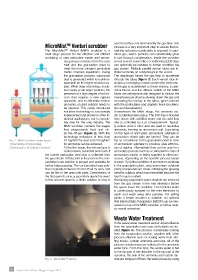
MicroMist  Venturi scrubber               used to further cool and humidify the gas flow. This
                                         TM
                                                                      process is a very important step to assure that re-
                            The MicroMist™ Venturi (MMV) scrubber is a   maining submicron particulate is exposed to satu-
                            multi-stage process for the effective and efficient   rated gas, where particles can substantially grow
                            scrubbing of urea particulate matter and ammo-  in size through condensation. Inside the scrubber
                                       nia gaseous residues from the urea   vessel several Dual-Orifice Conditioning (DOI) trays
                                       melt and the granulation plant to   can optionally be installed to further condition the
                                       meet the more stringent particulate   gas stream. Multiple parallel venturi tubes are in-
                                       matter emission regulations. During   stalled vertically on a diaphragm in the vessel.
                                       the granulation process, submicron   The diaphragm forces the gas flow to accelerate
                                       dust is generated which is mainly re-  through the tubes (figure 3). Each venturi tube in-
                                       sponsible for the higher emission va-  cludes a converging conical section (the inlet) whe-
                                       lues. While older technology scrub-  re the gas is accelerated to throat velocity, a cylin-
                                       bers easily scrub larger particles, the   drical throat, and the diffuser outlets of the MMV
                                       presence of a high degree of submi-  tubes are aerodynamically designed to reduce the
                                       cron dust requires a new capture   overall pressure drop by slowing down the gas and
                                       approach, and to efficiently remove   recovering the energy. In the tubes, gases interact
                                       ammonia, an acid solution needs to   with the particulates and droplets twice (accelera-
                                       be injected. This newly introduced   tion and deceleration).
                                       scrubber technology is successfully   Downstream  the  MMV  stage,  the  ammonia  aci-
                                       implemented and proven in other in-  dic scrubbing takes place. The DOI tray is flooded
                                       dustrial applications, but is comple-  from above with acidified water and the acid flow
                                       tely  new  for  the  urea  industry.  The   rate is controlled by a pH measurement. Typical-
                                       MMV scrubber contains five stages   ly sulfuric acid or nitric acid are used to neutralize
                                       that progressively treat and cle-  ammonia, forming an ammonium salt. Depending
                                       an the off-gas (figure 2). With this   on the type of acid used, ammonium sulphate or
                                       technology emissions of less than   ammonium nitrate salts are formed. They can be
       Fig. 2 - MMV Scrubber stages layout:    10 mg/Nm  for dust and 20 mg/Nm    fed as a feedstock to the granulation plant in case
                                                                   3
                                                3
       1) Quenching; 2) Subcooling;    for ammonia can be achieved.   of ammonium sulphate to produce urea with tra-
       3) Atomization; 4) Collection element  At the first stage, the exhaust gas is   ces of sulphur. Alternatively they can be used in a
                                       cooled down, saturated and most of   secondary process such as a UAN plant in case of
                            the coarse particulate urea dust is collected from   ammonium nitrate, or being supplied to other pro-
                            the gas stream At this point in the process the con-  cesses, depending on the specific process layout
                            centrated urea solution is purged and available for   chosen. By further addition of ammonium sulphate
                            further (re)processing. The concentrated urea solu-  in the granulation plant, urea ammonium sulphate
                            tion is typically between 35 and 45 wt-% urea, and   (UAS) compounds are made, satisfying the growing
                            can be fed to the urea melt plant. Downstream of   need for sulphur, which has meanwhile become the
                            the first quench zone, a secondary quench is used.   fourth macro nutrient.
                            In this second quench, a dilute solution of urea is   Remaining suspended water droplets are removed
                                                                      from the gas stream in the mist eliminator before
                                                                      the gases leave the scrubber. Fresh (clean) water
                                                                      is continuously sprayed on the mist eliminator to
                                                                      catch  and  wash  away dirty  particles.  For prilling
                                                                      plants a similar scrubber is available. An optional
                                                                      Wet ElectroStatic Precipitator (WESP) can be inte-
                                                                      grated on top of the MMV scrubber to further redu-
                                                                      ce overall emissions.

                                                                      Waste Water Treatment
                                                                      In the waste water treatment section liquid effluents
                                                                      from the granulation and urea melt plants are tre-
                                                                      ated (figure 4). The process condensate coming
                                                                      from the evaporation section, together with other
                                                                      process effluents such as sealing water from stuf-
                                                                      fing boxes, contain ammonia and urea. All of the
                                                                      process condensates are collected in the ammonia
                                                                      water tank. From this tank, the waste water is fed
                                                                      to the top part of the desorber. In the top part of the
                                                                      desorber, the bulk of the ammonia and carbon dio-
                            Fig. 3 - Micro Mist™ Venturi              xide are stripped off from the water phase by using


       42  Impiantistica Italiana - Maggio-Giugno 2018